
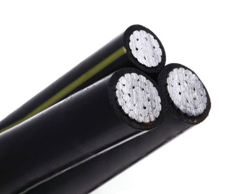
Product Overview
ABC (Aerial Bundled Cables or Aerial Bundled Conductors) are several phase conductors insulated and tightly bundled together with a bare neutral conductor for use in overhead power lines. It utilises the same principles as used for bundled conductors, but are much closer together and each one, except the neutral line, is surrounded by a layer of insulation. This is in direct contrast to the traditional use of uninsulated conductors which are separated by air gaps. LV (Low Voltage) ABC aluminium cables are already in use in many countries around the world.
Main advantages:
-
Safer and more reliable
-
Cheaper and more aesthetic
-
Less labour intensive and require less maintenance
-
Require less pruning and tree clearing
-
Eliminate the risk of bush fires initiated by conductor clashing and fallen trees
-
Simultaneous disconnection of all conductors eliminates potentially dangerous fault conditions when overhead power lines are broken by fallen trees or high vehicles
-
Less susceptible to vandalism and loss through theft
It provides a higher level of safety in difficult terrain including forest areas, coastal areas, and hilly areas. In climates with a high level of moisture, accelerated tree growth becomes a significant problem increasing the risk of bush fires. If aerial bundled conductors are touched by tree branches they will not arc over.
Application
Aerial Bundled Conductor cables can be used to replace bare conductor cables in overhead distribution systems. It is ideal for use in urban areas with congested power distribution and narrow lanes and by‑lanes. The flexible system is much easier than conventional overhead power lines to re‑route when demanded by changes in urban development plans.
ABC cables can be used in the following ways:
-
As replacement for bare overhead power lines in rural areas
-
In areas where space is limited such as narrow streets and lanes
-
In forests and woods where there is an increased risk of damage from fallen branches and trees
-
As replacement for bare overhead power lines where prime importance is placed on reliability of supply
-
Where supply voltage with a high degree of stability is required
-
As reinforcement for existing overhead power systems without having to increase voltage
-
In difficult terrain like hilly areas where the cost of installing underground cabling or overhead power lines is very high
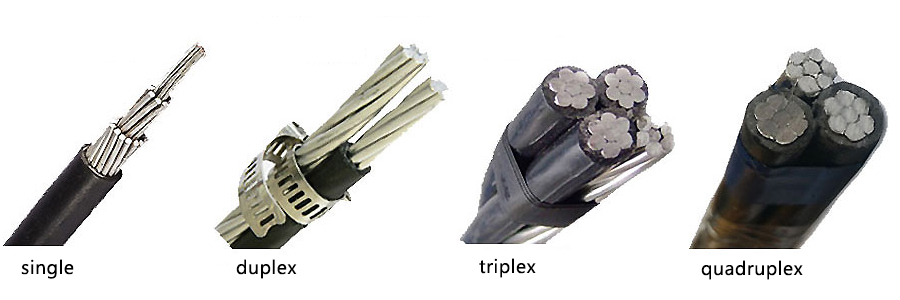
Two types of systems are available:
-
Self‑Supporting System – consisting of 4 cores of compacted aluminium hard drawn stranded conductors
-
Supporting Core System – consisting of 3 phase cores
Triplex wire is also an important product of ABC cable.
Standards
Basic design to:
-
BS 7870
-
TNB Specification (IEC 60502)
-
HD 626 S1
-
NFC 33‑209
-
AS/NZS 3560‑1
Technical Data
| Property | Value |
|---|---|
| Rated Voltage | 0.6/1 kV |
| Test Voltage | 4 Veff kV |
| Minimum Laying Temperature | -20°C |
| Operating Temperature | -40°C to +90°C |
| Maximum Short‑circuit Temperature | 250°C |
| Maximum Conductor Temperature | 80°C |
| Minimum Bending Radius | 18 × OD |
Specifications
| Property | Details |
|---|---|
| Voltage Level | Low Voltage (0.6/1 kV) |
| UV Resistance | ✓ (XLPE compound, UV‑resistant) |
| Working Temperature | 90°C |
| Cold Resistant | -40°C |
| Conductor Material | Aluminium, round stranded compressed (RM) |
| Insulation | XLPE compound, UV‑resistant |
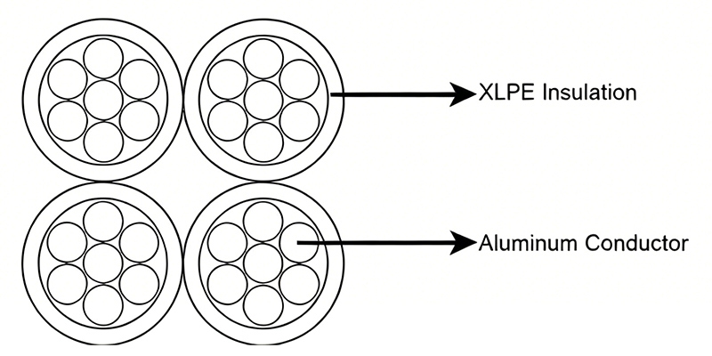
Construction
-
Conductor: Aluminium conductor, round stranded compressed (RM)
-
Insulation: XLPE compound, UV‑resistant
-
Core Identification:
-
1, 2 resp. 3 raised longitudinal ribs on the surface of the cores
-
Neutral core: at least 12 ribs for cross‑sections up to 50 mm²; at least 16 ribs for cores above 50 mm²
-
For five‑core bundles: surface of the protective core should be smooth
-
Technical Parameters
Table 1 – BS 7870 (LV ABC Cable)
| Number of Cores × Nominal Cross Section (mm²) | Overall Diameter (mm) | Weight (kg/km) | Max Conductor Resistance (Ω/km) | Min Breaking Load (kN) | Current Rating (A) |
|---|---|---|---|---|---|
| 1×16 RM | 8.0 | 74 | 1.910 | 2.5 | 72 |
| 1×25 RM | 9.0 | 106 | 1.200 | 4.0 | 107 |
| 1×35 RM | 10.5 | 138 | 0.868 | 5.5 | 132 |
| 1×50 RM | 11.8 | 182 | 0.641 | 8.0 | 165 |
| 1×70 RM | 13.0 | 252 | 0.443 | 10.7 | 205 |
| 1×95 RM | 15.4 | 333 | 0.320 | 13.7 | 240 |
| 1×120 RM | 17.0 | 408 | 0.253 | 18.6 | 290 |
| 1×150 RM | 19.0 | 502 | 0.206 | 23.2 | 334 |
| 1×185 RM | 21.0 | 611 | 0.164 | 28.7 | 389 |
| 1×240 RM | 24.0 | 801 | 0.125 | 37.2 | 467 |
| 2×16 RM | 15.6 | 147 | 1.910 | 2.5 | 72 |
| 2×25 RM | 18.0 | 208 | 1.200 | 4.0 | 107 |
| 2×35 RM | 20.0 | 277 | 0.868 | 5.5 | 132 |
| 2×50 RM | 23.5 | 361 | 0.641 | 8.0 | 165 |
| 2×70 RM | 25.4 | 505 | 0.443 | 10.7 | 205 |
| 2×95 RM | 30.3 | 666 | 0.320 | 13.7 | 240 |
| 2×150 RM | 38.0 | 1004 | 0.206 | 23.2 | 334 |
| 4×16 RM | 18.8 | 286 | 1.910 | 2.5 | 72 |
| 4×25 RM | 21.2 | 430 | 1.200 | 4.0 | 107 |
| 4×35 RM | 24.1 | 553 | 0.868 | 5.5 | 132 |
| 4×50 RM | 27.8 | 746 | 0.641 | 8.0 | 165 |
| 4×70 RM | 31.8 | 1009 | 0.443 | 10.7 | 205 |
| 4×95 RM | 37.8 | 1332 | 0.320 | 13.7 | 240 |
| 4×120 RM | 54.4 | 1632 | 0.253 | 18.6 | 290 |
| 4×50 + 1×25 RM | 31.9 | 814 | 0.641 / 1.200 | 8.0 / 4.0 | 165 / 107 |
| 4×50 + 1×35 RM | 31.9 | 845 | 0.641 / 0.868 | 8.5 / 5.5 | 165 / 132 |
| 4×70 + 1×25 RM | 36.0 | 1105 | 0.443 / 1.200 | 10.7 / 4.0 | 205 / 107 |
| 4×70 + 2×25 RM | 40.0 | 1217 | 0.443 / 1.200 | 10.7 / 4.0 | 205 / 107 |
| 4×95 + 1×25 RM | 41.8 | 1438 | 0.320 / 1.200 | 13.7 / 4.0 | 240 / 107 |
| 4×95 + 2×25 RM | 42.0 | 1544 | 0.320 / 1.200 | 13.7 / 4.0 | 240 / 107 |
| 4×120 + 1×25 RM | 59.0 | 2050 | 0.253 / 1.200 | 18.6 / 4.0 | 290 / 107 |
Table 2 – TNB Specification (IEC 60502) – 3‑core + neutral
| Number of Cores × Nominal Cross Section (mm²) | Overall Diameter (mm) | Weight (kg/km) | Max Conductor Resistance (Ω/km) | Min Breaking Load (kN) | Current Rating (A) |
|---|---|---|---|---|---|
| 1×16+1×25 RM | 15.3 | 160 | 1.910 | 2.5 | 72 |
| 3×16+1×25 RM | 19.0 | 290 | 1.200 | 4.0 | 107 |
| 3×25+1×25 RM | 23.2 | 400 | 0.868 | 5.5 | 132 |
| 3×35+1×25 RM | 25.6 | 500 | 0.641 | 8.0 | 165 |
| 3×50+1×35 RM | 30.0 | 680 | 0.443 | 10.7 | 205 |
| 3×70+1×50 RM | 34.9 | 920 | 0.320 | 13.7 | 240 |
| 3×95+1×70 RM | 40.6 | 1270 | 0.253 | 18.6 | 290 |
| 3×120+1×70 RM | 44.1 | 1510 | 0.206 | 23.2 | 334 |
| 3×150+1×95 RM | 49.2 | 1870 | 0.164 | 28.7 | 389 |
| 3×185+1×120 RM | 54.9 | 2340 | 0.125 | 37.2 | 467 |
| 3×25+1×25+1×16 RM | 23.2 | 470 | 1.910 | 2.5 | 72 |
| 3×35+1×25+1×16 RM | 25.6 | 560 | 1.200 | 4.0 | 107 |
| 3×50+1×35+1×16 RM | 30.0 | 740 | 0.868 | 5.5 | 132 |
| 3×70+1×50+1×16 RM | 34.9 | 980 | 0.641 | 8.0 | 165 |
| 3×95+1×70+1×16 RM | 40.6 | 1330 | 0.443 | 10.7 | 205 |
| 3×120+1×70+1×16 RM | 44.1 | 1580 | 0.320 | 13.7 | 240 |
| 3×150+1×95+1×16 RM | 49.2 | 1940 | 0.206 | 23.2 | 334 |
| 3×185+1×120+1×16 RM | 54.9 | 2410 | 1.910 | 2.5 | 72 |
Table 3 – HD 626 S1 (ABC Cable)
| Number of Cores × Nominal Cross Section (mm²) | Outer Diameter (mm) | Total Weight (kg/km) | Max Conductor Resistance (Ω/km) | Min Breaking Load of Conductor Strand (kN) | Current Rating in Air (A) |
|---|---|---|---|---|---|
| 2×16 RM | 15.6 | 147 | 1.910 | 2.5 | 72 |
| 2×25 RM | 18.0 | 208 | 1.200 | 4.0 | 107 |
| 2×35 RM | 20.0 | 277 | 0.868 | 5.5 | 132 |
| 2×50 RM | 23.5 | 361 | 0.641 | 8.0 | 165 |
| 4×16 RM | 18.8 | 286 | 1.910 | 2.5 | 72 |
| 4×25 RM | 21.2 | 430 | 1.200 | 4.0 | 107 |
| 4×35 RM | 24.1 | 553 | 0.868 | 5.5 | 132 |
| 4×50 RM | 27.8 | 746 | 0.641 | 8.0 | 165 |
| 4×70 RM | 31.8 | 1009 | 0.443 | 10.7 | 205 |
| 4×95 RM | 37.8 | 1332 | 0.320 | 13.7 | 240 |
| 4×120 RM | 54.4 | 1632 | 0.253 | 18.6 | 290 |
| 4×35 + 1×35 RM | 30.0 | 694 | 0.868 / 0.868 | 5.5 / 5.5 | 132 / 132 |
| 4×50 + 1×25 RM | 31.9 | 814 | 0.641 / 1.200 | 8.0 / 4.0 | 165 / 107 |
| 4×50 + 1×35 RM | 31.9 | 845 | 0.641 / 0.868 | 8.5 / 5.5 | 165 / 132 |
| 4×70 + 1×25 RM | 36.0 | 1105 | 0.443 / 1.200 | 10.7 / 4.0 | 205 / 107 |
| 4×70 + 2×25 RM | 40.0 | 1217 | 0.443 / 1.200 | 10.7 / 4.0 | 205 / 107 |
| 4×70 + 1×35 RM | 36.2 | 1150 | 0.443 / 0.868 | 10.7 / 5.5 | 205 / 132 |
| 4×70 + 2×35 RM | 40.1 | 1289 | 0.443 / 0.868 | 10.7 / 5.5 | 205 / 132 |
| 4×95 + 1×25 RM | 41.8 | 1438 | 0.320 / 1.200 | 13.7 / 4.0 | 240 / 107 |
| 4×95 + 1×35 RM | 41.8 | 1467 | 0.320 / 0.868 | 13.7 / 5.5 | 240 / 132 |
| 4×95 + 2×25 RM | 42.0 | 1544 | 0.320 / 1.200 | 13.7 / 4.0 | 240 / 107 |
Table 4 – NFC 33‑209 (ABC Cable)
| Number of Cores × Nominal Cross Section (mm²) | Overall Diameter (mm) | Weight (kg/km) | Max Conductor Resistance (Ω/km) | Min Breaking Load (kN) | Current Rating (A) |
|---|---|---|---|---|---|
| 2×10 RM | 12.8 | 93 | 3.080 | 1.5 | 38 |
| 4×10 RM | 15.4 | 183 | 3.080 | 1.5 | 38 |
| 2×16 RM | 14.8 | 129 | 1.910 | 2.3 | 72 |
| 2×16 RN + 2×1.5 RE | 14.8 | 176 | 1.910 / 12.100 | 2.3 | 72 |
| 4×16 RM | 17.8 | 257 | 1.910 | 2.3 | 72 |
| 4×16 RN + 2×1.5 RE | 17.8 | 304 | 1.910 / 12.100 | 2.3 | 72 |
| 2×25 RM | 18.0 | 202 | 1.200 | 3.8 | 107 |
| 2×25 RM + 2×1.5 RE | 18.0 | 249 | 1.200 / 12.100 | 3.8 | 107 |
| 4×25 RM | 21.7 | 404 | 1.200 | 3.8 | 107 |
| 4×25 RM + 2×1.5 RE | 21.7 | 451 | 1.200 / 12.100 | 3.8 | 107 |
| 2×35 RM | 20.8 | 269 | 0.868 | 5.2 | 132 |
| 2×35 RM + 2×1.5 RE | 20.8 | 316 | 0.868 / 12.100 | 5.2 | 132 |
| 4×35 RM | 25.1 | 539 | 0.868 | 5.2 | 132 |
| 4×35 RM + 2×1.5 RE | 25.1 | 586 | 0.868 / 12.100 | 5.2 | 132 |
| 2×50 RM | 23.4 | 352 | 0.641 | 7.6 | 165 |
| 2×50 RM + 2×1.5 RE | 23.4 | 399 | 0.641 / 12.100 | 7.6 | 165 |
| 1×54.6 RM + 3×25 RM | 21.7 | 507 | 0.630 / 1.200 | 3.8 | 107 |
| 1×54.6 RM + 3×25 RM + 1×16 RM | 24.3 | 573 | 0.630 / 1.200 / 1.910 | 3.8 / 2.3 | 107 / 72 |
| 1×54.6 RM + 3×25 RM + 2×16 RM | 29.7 | 639 | 0.630 / 1.200 / 1.910 | 3.8 / 2.3 | 107 / 72 |
| 1×54.6 RM + 3×25 RM + 3×16 RM | 31.1 | 705 | 0.630 / 1.200 / 1.910 | 3.8 / 2.3 | 107 / 72 |
| 1×54.6 RM + 3×35 RM | 25.1 | 615 | 0.630 / 0.868 | 5.2 | 132 |
| 1×54.6 RM + 3×35 RM + 1×16 RM | 28.1 | 680 | 0.630 / 0.868 / 1.910 | 5.2 / 2.3 | 132 / 72 |
| 1×54.6 RM + 3×35 RM + 2×16 RM | 34.3 | 748 | 0.630 / 0.868 / 1.910 | 5.2 / 2.3 | 132 / 72 |
| 1×54.6 RM + 3×35 RM + 3×16 RM | 35.9 | 814 | 0.630 / 0.868 / 1.910 | 5.2 / 2.3 | 132 / 72 |
| 1×54.6 RM + 3×35 RM + 1×25 RM | 28.1 | 714 | 0.630 / 0.868 / 1.200 | 5.2 / 3.8 | 132 / 107 |
| 1×54.6 RM + 3×50 RM | 28.2 | 741 | 0.630 / 0.641 | 7.6 | 165 |
| 1×54.6 RM + 3×50 RM + 1×16 RM | 31.6 | 806 | 0.630 / 0.641 / 1.910 | 7.6 / 2.3 | 165 / 72 |
| 1×54.6 RM + 3×50 RM + 2×16 RM | 38.6 | 875 | 0.630 / 0.641 / 1.910 | 7.6 / 2.3 | 165 / 72 |
| 1×54.6 RM + 3×50 RM + 3×16 RM | 40.4 | 940 | 0.630 / 0.641 / 1.910 | 7.6 / 2.3 | 165 / 72 |
| 1×54.6 RM + 3×50 RM + 1×25 RM | 31.6 | 841 | 0.630 / 0.641 / 1.200 | 7.6 / 3.8 | 165 / 107 |
| 1×54.6 RM + 3×70 RM | 33.0 | 950 | 0.630 / 0.443 | 10.2 | 205 |
| 1×54.6 RM + 3×70 RM + 1×16 RM | 37.0 | 1014 | 0.630 / 0.443 / 1.910 | 10.2 / 2.3 | 205 / 72 |
| 1×54.6 RM + 3×70 RM + 2×16 RM | 45.2 | 1083 | 0.630 / 0.443 / 1.910 | 10.2 / 2.3 | 205 / 72 |
| 1×54.6 RM + 3×70 RM + 3×16 RM | 47.3 | 1148 | 0.630 / 0.443 / 1.910 | 10.2 / 2.3 | 205 / 72 |
| 1×54.6 RM + 3×70 RM + 1×25 RM | 37.0 | 1048 | 0.630 / 0.443 / 1.200 | 10.2 / 3.8 | 205 / 107 |
| 1×54.6 RM + 3×70 RM + 2×25 RM | 45.2 | 1150 | 0.630 / 0.443 / 1.200 | 10.2 / 3.8 | 205 / 107 |
| 1×54.6 RM + 3×70 RM + 3×25 RM | 47.3 | 1250 | 0.630 / 0.443 / 1.200 | 10.2 / 3.8 | 205 / 107 |
| 1×54.6 RM + 3×95 RM | 37.4 | 1176 | 0.630 / 0.320 | 13.5 | 240 |
| 1×54.6 RM + 3×95 RM + 1×16 RM | 41.9 | 1243 | 0.630 / 0.320 / 1.910 | 13.5 / 2.3 | 240 / 72 |
Table 5 – AS/NZS 3560 Part 1 (LV ABC Cable)
| Number of Cores × Nominal Cross Section (mm²) | Overall Diameter (mm) | Weight (kg/km) | Minimum Breaking Load (kN) | Current Rating (A) |
|---|---|---|---|---|
| 2×16 RM | 15.0 | 140 | 4.4 | 78 |
| 2×25 RM | 17.6 | 210 | 7.0 | 105 |
| 2×35 RM | 19.6 | 270 | 9.8 | 125 |
| 2×50 RM | 22.8 | 370 | 11.4 | 150 |
| 2×95 RM | 30.6 | 680 | 15.3 | 230 |
| 3×25 RM | 19.0 | 310 | 8.8 | 97 |
| 3×35 RM | 21.1 | 410 | 9.8 | 120 |
| 3×50 RM | 24.6 | 550 | 11.4 | 140 |
| 4×16 RM | 18.1 | 290 | 8.8 | 74 |
| 4×25 RM | 21.2 | 410 | 14.0 | 97 |
| 4×35 RM | 23.7 | 550 | 19.6 | 120 |
| 4×50 RM | 27.5 | 740 | 28.0 | 140 |
| 4×70 RM | 31.9 | 1000 | 39.2 | 175 |
| 4×95 RM | 36.9 | 1370 | 53.2 | 215 |
| 4×120 RM | 40.6 | 1690 | 67.2 | 250 |
| 4×150 RM | 43.9 | 2020 | 84.0 | 280 |