
Product Overview
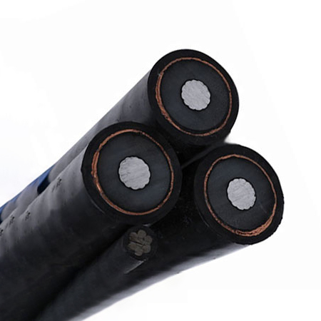
Aerial bundled cables are mainly used for secondary overhead lines on poles or as feeders to residential premises. This medium voltage ABC cable offers a compact, reliable, and safe solution for overhead power distribution in urban and rural networks.
Standards: Basic design to IEC 60502 / AS/NZS 3599‑1.
Specifications
| Property | Details |
|---|---|
| Voltage Level | Medium Voltage |
| Rated Voltages | 6.35/11 kV, 12.7/22 kV, 19/33 kV |
| Insulation | XLPE |
| Outer Sheath | HDPE |
| Support Messenger | Galvanized steel wires |
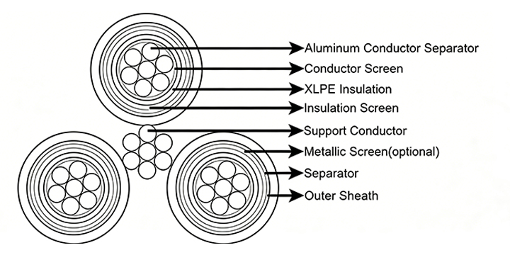
Construction
-
Phase Conductor: Circular compacted stranded H68 aluminium to BS2627
-
Conductor Screen: Extruded semi‑conductive layer
-
Insulation: XLPE
-
Insulation Screen: Extruded semi‑conductive layer
-
Metallic Screen (optional): Copper wire screen or copper tape screen
-
Separator: Semi‑conductive swellable tape
-
Outer Sheath: HDPE
-
Support Conductor: Galvanized steel wires
-
Assembly: Three XLPE insulated screened cores are bundled around the galvanized steel wires in a right‑hand lay
Technical Parameters
IEC 60502 – 6.35/11 kV ABC for Overhead Distribution Lines
| Number of Cores × Nominal Cross Section (mm²) | Phase Conductor | Messenger Suspension Unit | Continuous Current Rating at 30°C Ambient (A) | ||||
|---|---|---|---|---|---|---|---|
| Stranding (No.×mm) | Nominal Sectional Area (mm²) | Max Conductor Resistance (Ω/km) | Stranding (No.×mm) | Nominal Sectional Area (mm²) | Breaking Load (kN) | ||
| 3×50 + 1×25 | 19/1.78 | 50 | 0.641 | 7/3.0 | 50 | 60 | 116 |
| 3×70 + 1×50 | 19/.14 | 70 | 0.443 | 7/3.15 | 50 | 62 | 210 |
| 3×95 + 1×50 | 19/2.52 | 95 | 0.32 | 7/3.0 | 50 | 60 | 173 |
| 3×185 + 1×120 | 37/2.52 | 185 | 0.164 | 7/4.67 | 120 | 150 | 259 |
| 3×150 + 1×50 | 37/2.25 | 150 | 0.206 | 7/3.15 | 50 | 62 | 365 |
| 3×240 + 1×50 | 61/2.25 | 240 | 0.125 | 7/3.15 | 50 | 62 | 500 |
IEC 60502 – 19/33 kV ABC for Overhead Distribution Lines
| Number of Cores × Nominal Cross Section (mm²) | Phase Conductor | Messenger Suspension Unit | Continuous Current Rating at 30°C Ambient (A) | ||||
|---|---|---|---|---|---|---|---|
| Stranding (No.×mm) | Nominal Sectional Area (mm²) | Max Conductor Resistance (Ω/km) | Stranding (No.×mm) | Nominal Sectional Area (mm²) | Breaking Load (kN) | ||
| 3×50 + 1×50 | 19/1.78 | 50 | 0.641 | 7/3.0 | 50 | 60 | 165 |
| 3×150 + 1×50 | 37/2.25 | 150 | 0.206 | 7/3.0 | 50 | 60 | 315 |
| 3×185 + 1×70 | 37/2.52 | 185 | 0.164 | 7/3.57 | 70 | 91 | 355 |
| 3×70 + 1×50 | 19/2.14 | 70 | 0.443 | 7/3.15 | 50 | 62 | 250 |
| 3×150 + 1×50 | 37/2.25 | 150 | 0.206 | 7/3.15 | 50 | 62 | 370 |
AS/NZS 3599 Part 1 – 6.35/11 kV Al/XLPE/HDPE Non‑Screened Cables
| Number of Cores × Nominal Cross Section (mm²) | Phase Conductor | Messenger Suspension Unit | Nominal Sectional Area (mm²) | Breaking Load (kN) | |||
|---|---|---|---|---|---|---|---|
| Diameter of Conductor (mm) | Thickness of Insulation (mm) | Thickness of Insulation Screen (mm) | Thickness of Sheath (mm) | Stranding (No.×mm) | |||
| 3×35 | 6.9 | 3.4 | 0.8 | 1.2 | 7/4.75 | 52.4 | 1370 |
| 3×50 | 8.1 | 3.4 | 0.8 | 1.2 | 7/4.75 | 54.6 | 1530 |
| 3×70 | 9.7 | 3.4 | 0.8 | 1.2 | 7/4.75 | 57.8 | 1790 |
| 3×95 | 11.4 | 3.4 | 0.8 | 1.2 | 7/4.75 | 61.3 | 2100 |
| 3×120 | 12.8 | 3.4 | 0.8 | 1.2 | 19/3.50 | 67.3 | 2540 |
| 3×150 | 14.2 | 3.4 | 0.8 | 1.2 | 19/3.50 | 70.1 | 2840 |
| 3×185 | 15.7 | 3.4 | 0.8 | 1.2 | 19/3.50 | 73.1 | 3190 |
AS/NZS 3599 Part 1 – 6.35/11 kV Al/XLPE/CWS/HDPE Screened Cables
Light Duty Screen
| Number of Cores × Nominal Cross Section (mm²) | Diameter of Conductor (mm) | Thickness of Insulation (mm) | Thickness of Insulation Screen (mm) | Copper Wire Screen Stranding (No.×mm) | Thickness of Sheath (mm) | Galvanized Steel Wire Stranding (No.×mm) | Nominal Sectional Area (mm²) | Breaking Load (kN) |
|---|---|---|---|---|---|---|---|---|
| 3×35 | 6.9 | 3.4 | 0.8 | 25/0.85 | 1.8 | 7/2.00 | 54.1 | 1820 |
| 3×35 | 6.9 | 3.4 | 0.8 | 25/0.85 | 1.8 | 19/2.00 | 58.1 | 2130 |
| 3×50 | 8.1 | 3.4 | 0.8 | 25/0.85 | 1.8 | 19/2.00 | 60.4 | 2300 |
| 3×70 | 9.7 | 3.4 | 0.8 | 25/0.85 | 1.8 | 19/2.00 | 63.6 | 2570 |
| 3×95 | 11.4 | 3.4 | 0.8 | 25/0.85 | 1.8 | 19/2.00 | 67.0 | 2900 |
| 3×120 | 12.8 | 3.4 | 0.8 | 25/0.85 | 1.8 | 19/2.00 | 69.8 | 3190 |
| 3×150 | 14.2 | 3.4 | 0.8 | 25/0.85 | 1.9 | 19/2.00 | 73.0 | 3530 |
| 3×185 | 15.7 | 3.4 | 0.8 | 25/0.85 | 1.9 | 19/2.00 | 76.0 | 3890 |
Heavy Duty Screen
| Number of Cores × Nominal Cross Section (mm²) | Diameter of Conductor (mm) | Thickness of Insulation (mm) | Thickness of Insulation Screen (mm) | Copper Wire Screen Stranding (No.×mm) | Thickness of Sheath (mm) | Galvanized Steel Wire Stranding (No.×mm) | Nominal Sectional Area (mm²) | Breaking Load (kN) |
|---|---|---|---|---|---|---|---|---|
| 3×35 | 6.9 | 3.4 | 0.8 | 40/0.85 | 1.8 | 7/2.00 | 54.1 | 2050 |
| 3×35 | 6.9 | 3.4 | 0.8 | 40/0.85 | 1.8 | 19/2.00 | 58.1 | 2360 |
| 3×50 | 8.1 | 3.4 | 0.8 | 23/1.35 | 1.8 | 19/2.00 | 62.4 | 2820 |
| 3×70 | 9.7 | 3.4 | 0.8 | 32/1.35 | 1.8 | 19/2.00 | 65.6 | 3440 |
| 3×95 | 11.4 | 3.4 | 0.8 | 39/1.35 | 1.8 | 19/2.00 | 69.0 | 4030 |
| 3×120 | 12.8 | 3.4 | 0.8 | 39/1.35 | 1.8 | 19/2.00 | 71.8 | 4320 |
| 3×150 | 14.2 | 3.4 | 0.8 | 39/1.35 | 1.9 | 19/2.00 | 75.0 | 4670 |
| 3×185 | 15.7 | 3.4 | 0.8 | 39/1.35 | 1.9 | 19/2.00 | 78.0 | 5020 |
AS/NZS 3599 Part 1 – 12.7/22 kV Al/XLPE/HDPE Non‑Screened Cables
| Number of Cores × Nominal Cross Section (mm²) | Phase Conductor | Messenger Suspension Unit | Nominal Sectional Area (mm²) | Breaking Load (kN) | |||
|---|---|---|---|---|---|---|---|
| Diameter of Conductor (mm) | Thickness of Insulation (mm) | Thickness of Insulation Screen (mm) | Thickness of Sheath (mm) | Stranding (No.×mm) | |||
| 3×35 | 6.9 | 5.5 | 0.8 | 1.2 | 7/4.75 | 61.0 | 1780 |
| 3×50 | 8.1 | 5.5 | 0.8 | 1.2 | 7/4.75 | 63.3 | 1970 |
| 3×70 | 9.7 | 5.5 | 0.8 | 1.2 | 7/4.75 | 66.5 | 2260 |
| 3×95 | 11.4 | 5.5 | 0.8 | 1.2 | 7/4.75 | 69.9 | 2600 |
| 3×120 | 12.8 | 5.5 | 0.8 | 1.2 | 19/3.50 | 75.9 | 3070 |
| 3×150 | 14.2 | 5.5 | 0.8 | 1.2 | 19/3.50 | 78.7 | 3390 |
| 3×185 | 15.7 | 5.5 | 0.8 | 1.2 | 19/3.50 | 81.7 | 3760 |
AS/NZS 3599 Part 1 – 12.7/22 kV Al/XLPE/CWS/HDPE Screened Cables
Light Duty Screen
| Number of Cores × Nominal Cross Section (mm²) | Diameter of Conductor (mm) | Thickness of Insulation (mm) | Thickness of Insulation Screen (mm) | Copper Wire Screen Stranding (No.×mm) | Thickness of Sheath (mm) | Galvanized Steel Wire Stranding (No.×mm) | Nominal Sectional Area (mm²) | Breaking Load (kN) |
|---|---|---|---|---|---|---|---|---|
| 3×35 | 6.9 | 5.5 | 0.8 | 25/0.85 | 1.8 | 7/2.00 | 62.7 | 2280 |
| 3×35 | 6.9 | 5.5 | 0.8 | 25/0.85 | 1.8 | 19/2.00 | 66.7 | 2580 |
| 3×50 | 8.1 | 5.5 | 0.8 | 25/0.85 | 1.8 | 19/2.00 | 69.0 | 2780 |
| 3×70 | 9.7 | 5.5 | 0.8 | 25/0.85 | 1.9 | 19/2.00 | 72.6 | 3110 |
| 3×95 | 11.4 | 5.5 | 0.8 | 25/0.85 | 1.9 | 19/2.00 | 76.0 | 3460 |
| 3×120 | 12.8 | 5.5 | 0.8 | 25/0.85 | 2.0 | 19/2.00 | 79.2 | 3810 |
| 3×150 | 14.2 | 5.5 | 1.0 | 25/0.85 | 2.0 | 19/2.00 | 82.8 | 4230 |
| 3×185 | 15.7 | 5.5 | 1.0 | 25/0.85 | 2.1 | 19/2.00 | 86.2 | 4650 |
Heavy Duty Screen
| Number of Cores × Nominal Cross Section (mm²) | Diameter of Conductor (mm) | Thickness of Insulation (mm) | Thickness of Insulation Screen (mm) | Copper Wire Screen Stranding (No.×mm) | Thickness of Sheath (mm) | Galvanized Steel Wire Stranding (No.×mm) | Nominal Sectional Area (mm²) | Breaking Load (kN) |
|---|---|---|---|---|---|---|---|---|
| 3×35 | 6.9 | 5.5 | 0.8 | 40/0.85 | 1.8 | 7/2.00 | 62.7 | 2510 |
| 3×35 | 6.9 | 5.5 | 0.8 | 40/0.85 | 1.8 | 19/2.00 | 66.7 | 2810 |
| 3×50 | 8.1 | 5.5 | 0.8 | 23/1.35 | 1.8 | 19/2.00 | 71.0 | 3300 |
| 3×70 | 9.7 | 5.5 | 0.8 | 32/1.35 | 1.9 | 19/2.00 | 74.6 | 3970 |
| 3×95 | 11.4 | 5.5 | 0.8 | 39/1.35 | 1.9 | 19/2.00 | 78.0 | 4600 |
| 3×120 | 12.8 | 5.5 | 0.8 | 39/1.35 | 2.0 | 19/2.00 | 81.2 | 4950 |
| 3×150 | 14.2 | 5.5 | 1.0 | 39/1.35 | 2.0 | 19/2.00 | 84.8 | 5360 |
| 3×185 | 15.7 | 5.5 | 1.0 | 39/1.35 | 2.1 | 19/2.00 | 88.2 | 5790 |
Continuous Current Ratings (General) – for MV ABC Cables
| Nominal Cross Section (mm²) | Continuous Current Rating (A) | ||
|---|---|---|---|
| Still air | 1 m/s wind | 2 m/s wind | |
| 35 | 105 | 145 | 165 |
| 50 | 125 | 170 | 200 |
| 70 | 150 | 215 | 250 |
| 95 | 180 | 260 | 300 |
| 120 | 205 | 300 | 350 |
| 150 | 230 | 340 | 395 |
| 185 | 265 | 390 | 450 |