
Product Overview
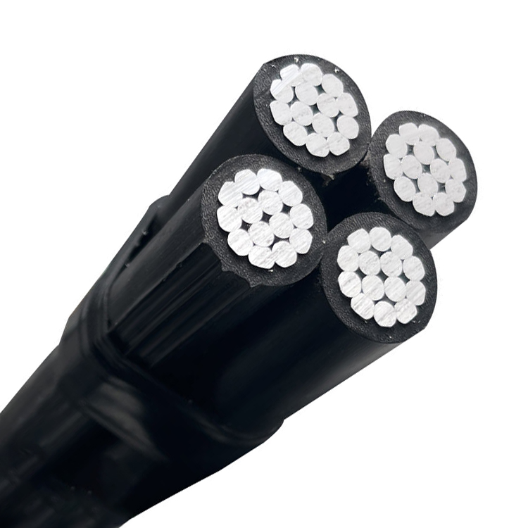
Self‑supporting overhead cable bundle, applied for electric power distribution in low voltage metropolitan, suburban and rural networks, for public lighting and house connections. Laid on pillars, consoles and house fronts.
Standards: HRN HD 626 S1 / DIN VDE 0276 part 626
Technical Data
| Property | Value |
|---|---|
| Temperature during installation | -5°C |
| Operating temperature | -30°C up to +80°C |
| Short circuit (max. 5 s) | 130°C |
| Nominal voltage | U₀/U = 0.6/1 kV |
| Test voltage | 4 kV |
| Minimum inner bending radius | 12 × OD |
Abbreviation
| Code | Meaning |
|---|---|
| N | Standard Cable type |
| F | Facade Cable |
| A | Aluminium conductor |
| 2X | XLPE insulation |
| +N | with ‘Messenger’ Core |
Round stranded conductor for all sizes connection derived from the distribution system.
Specifications
| Property | Details |
|---|---|
| Voltage Level | Low Voltage (0.6/1 kV) |
| Conductor Material (Phase) | Aluminium, round multi‑wire stranded compacted (RM), class 2 |
| Conductor Material (Neutral/Support) | Aluminium alloy, round multi‑wire stranded compacted (RM), class 2 |
| Insulation | XLPE (cross‑linked polyethylene, PE‑X) compound TIX‑2 or TIX‑5 |
| Insulation Colour | Black |
Construction
-
Phase Conductor: Round Al conductor, multi wire stranded compacted (RM), class 2 according to HRN HD 383. Phase conductors are marked with longitudinal protrusions (one, two or three).
-
Neutral (supporting) conductor: Round conductor, multi wire stranded compacted (RM), class 2 according to HRN HD 383, of aluminium alloy.
-
Insulation: XLPE (cross‑linked polyethylene, recent mark: PE‑X) compound TIX‑2 or TIX‑5 according to HD 626 S1.
-
Insulation colour: Black.
Technical Parameters
Phase Conductors and Neutral Conductor – Dimensions
| Conductor Type | Nominal Cross‑section (mm²) | Stranding (No. of wires) | External diameter min. (mm) | External diameter max. (mm) | Conductor resistance at 20°C max. (Ω/km) | Insulation thickness (mm) | Diameter with insulation min. (mm) | Diameter with insulation max. (mm) |
|---|---|---|---|---|---|---|---|---|
| Phase conductor | ||||||||
| 16 | 7 | 4.6 | 5.1 | 1.910 | 1.2 | 7.0 | 7.8 | |
| 25 | 7 | 5.8 | 6.3 | 1.200 | 1.4 | 8.6 | 9.4 | |
| 35 | 7 | 6.8 | 7.3 | 0.868 | 1.6 | 10.0 | 10.9 | |
| 50 | 7 | 7.9 | 8.4 | 0.641 | 1.6 | 11.1 | 12.0 | |
| 70 | 19 | 9.7 | 10.2 | 0.443 | 1.8 | 13.3 | 14.2 | |
| Neutral conductor | ||||||||
| 71.5 (AlMg1) | 7 | 10.2 | 10.6 | 0.470 | 1.8 | – | 14.6 | |
| 70 (AlMgSi) | 7 | 10.0 | 10.2 | 0.500 | 1.6 | 12.9 | 13.6 |
Bundle Construction – Lay, Diameter and Weight
| Construction of bundle (N × mm²) | Lay of stranding (mm) | Bundle diameter (mm) | Al weight (kg/km) | Bundle weight (kg/km) |
|---|---|---|---|---|
| 2×16 | 300 | 15.0 | 93 | 137 |
| 4×16 | 350 | 18.0 | 186 | 270 |
| 2×25 | 350 | 18.4 | 145 | 214 |
| 4×25 | 430 | 22.2 | 290 | 431 |
| 3×25 + 70 | 700 | 26.6 | 421 | 569 |
| 3×25 + 70 + 1×16 | 700 | 26.6 | 467 | 672 |
| 3×25 + 70 + 2×16 | 700 | 29.6 | 513 | 739 |
| 3×35 + 70 | 760 | 29.8 | 509 | 688 |
| 3×35 + 70 + 1×16 | 760 | 29.8 | 555 | 759 |
| 3×35 + 70 + 2×16 | 760 | 29.8 | 602 | 825 |
| 3×50 + 70 | 850 | 33.1 | 639 | 809 |
| 3×50 + 70 + 1×16 | 850 | 33.1 | 685 | 879 |
| 3×50 + 70 + 2×16 | 850 | 33.1 | 732 | 945 |
| 3×70 + 70 | 980 | 38.6 | 813 | 1,044 |
| 3×70 + 70 + 1×16 | 980 | 38.6 | 860 | 1,114 |
| 3×70 + 70 + 2×16 | 980 | 38.6 | 907 | 1,181 |
| 3×70 + 70 + 2×25 | 980 | 38.6 | 958 | 1,253 |