
Product Overview
This 0.6/1kV PVC insulated, PVC sheathed unarmored cable with two cores and an earth conductor is designed for mains, submains, and subcircuits in buildings and industrial plants. Suitable for installation unenclosed, in conduit, buried direct, or in underground ducts where mechanical damage is not expected. Manufactured to Australian/New Zealand standards, it ensures reliable power distribution with V-90 PVC insulation and 5V-90 PVC sheath.
Applications
-
Mains, submains, and subcircuit wiring
-
Unenclosed installations
-
Enclosed in conduit
-
Direct burial
-
Underground ducts
-
Buildings and industrial plants (not subject to mechanical damage)
Standards
-
AS/NZS 5000.1
-
AS/NZS 3008
-
AS/NZS 1125
-
IEC 60502-1
Specifications at a Glance
| Property | Detail |
|---|---|
| Voltage rating | 0.6/1 kV |
| Conductor | Plain annealed copper |
| Insulation | PVC V-90 |
| Insulation colours | Red, Black, Green/Yellow (earth) |
| Sheath | PVC 5V-90 |
| Sheath colour | Black (other colours on request) |
| Number of cores | 2 + Earth |
| Armour | Unarmored |
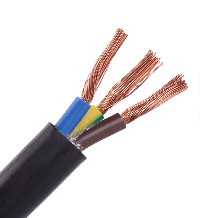
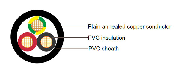
Cable Construction
-
Conductor
Plain annealed copper, circular stranded. -
Insulation
Polyvinyl chloride (PVC) compound type V-90.
Colour coding: Red, Black (phase), Green/Yellow (earth). -
Sheath
Polyvinyl chloride (PVC) compound type 5V-90.
Colour: Black (other colours available upon request).
Technical Parameters
Table 1 – Current Ratings & Electrical Characteristics (AS/NZS 3008)
| Nominal Area (mm²) | Unenclosed in Air (A) | Buried Direct (A) | Buried in Ducts (A) | Max DC Resistance @20°C (Ω/km) | Max AC Resistance @75°C (Ω/km) | Reactance (Ω/km) | Single Phase Voltage Drop @75°C (mV/A·m) |
|---|---|---|---|---|---|---|---|
| 1.5 | 18 | 14 | 22 | 13.6 | 16.5 | 0.111 | 33.0 |
| 2.5 | 26 | 20 | 31 | 7.41 | 9.01 | 0.102 | 18.0 |
| 4 | 34 | 26 | 40 | 4.61 | 5.61 | 0.102 | 11.2 |
| 6 | 44 | 34 | 51 | 3.08 | 3.75 | 0.0967 | 7.50 |
| 10 | 60 | 47 | 68 | 1.83 | 2.23 | 0.0906 | 4.46 |
| 16 | 80 | 63 | 88 | 1.15 | 1.40 | 0.0861 | 2.81 |
| 25 | 105 | 88 | 115 | 0.727 | 0.884 | 0.0853 | 1.78 |
| 35 | 130 | 105 | 140 | 0.524 | 0.638 | 0.0826 | 1.28 |
| 50 | 160 | 125 | 165 | 0.387 | 0.471 | 0.0797 | 0.957 |
| 70 | 200 | 155 | 205 | 0.268 | 0.327 | 0.0770 | 0.673 |
| 95 | 250 | 190 | 250 | 0.193 | 0.236 | 0.0766 | 0.498 |
Table 2 – Construction Details
| Nom. Conductor Area (mm²) | Conductor No./Diameter (mm) | Nom. Insulation Thickness (mm) | Nom. Earth Conductor Area (mm²) | Nom. Earth Conductor Insulation Thickness (mm) | Nom. Overall Diameter (mm) | Approx. Mass (kg/km) |
|---|---|---|---|---|---|---|
| 1.5 | 7/0.50 | 0.8 | 1.5 | 0.6 | 10.6 | 160 |
| 2.5 | 7/0.67 | 0.8 | 2.5 | 0.7 | 11.6 | 220 |
| 4 | 7/0.85 | 1.0 | 2.5 | 0.7 | 13.1 | 295 |
| 6 | 7/1.04 | 1.0 | 2.5 | 0.7 | 14.2 | 335 |
| 10 | 7/1.35 | 1.0 | 4 | 1.0 | 15.9 | 440 |
| 16 | 7/1.70 | 1.0 | 6 | 1.0 | 17.9 | 620 |
| 25 | 7/2.14 | 1.2 | 6 | 1.0 | 21.6 | 840 |
| 35 | 7/2.65 | 1.2 | 10 | 1.0 | 22.8 | 1090 |
| 50 | 19/1.89 | 1.4 | 16 | 1.0 | 25.8 | 1465 |
| 70 | 19/2.24 | 1.4 | 25 | 1.2 | 30.4 | 1900 |
| 95 | 19/2.65 | 1.6 | 25 | 1.2 | 34.8 | 2500 |