
Product Overview
Our Tight Buffer Optical Fiber Cables are specifically engineered for reliable data transmission in demanding marine and offshore environments. These cables meet the highest safety standards with low smoke, zero halogen (LSZH), and fire retardant properties, making them ideal for use on ships and particularly in cruise ships where passenger and crew safety is paramount.
Key Features
-
Marine-Grade Safety: LSZH Fire Retardant sheath minimizes smoke and toxic emissions
-
Robust Construction: Designed to withstand harsh marine environments
-
Water Resistance: Reinforcing elements with watertight tape protection
-
Comprehensive Compliance: Meets international IEC standards for fire safety
-
Flexible Installation: Optimized bending radius for easy routing
-
Wide Temperature Range: Suitable for -20°C to +60°C operations
Applications
-
Data transmission networks on ships and vessels
-
Cruise ship communication and control systems
-
Offshore platform data links
-
Marine applications requiring enhanced fire safety (LSZH)
-
Shipboard data infrastructure
-
Naval communication systems
Standards Compliance
This cable construction complies with the following IEC standards:
-
IEC 60332-1-2 Test for vertical flame propagation for a single insulated wire or cable
-
IEC 60332-3-22 Test for vertical flame spread of bunched wires or cables
-
IEC 60754-1/2 Test on gases evolved during combustion of materials from cables
-
IEC 61034 Measurement of smoke density of cables burning under defined conditions
Construction Details
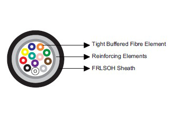
-
Coated Optical Fiber: 250/900μm
-
Reinforcing Elements: Glass yarns with watertight tape
-
Outer Sheath: Low Smoke Zero Halogen (LSOH) and Fire Retardant (FR) compound
-
Design: Tight buffer construction for enhanced mechanical protection
Fiber Types & Specifications
We offer a range of fiber types to suit various application needs, as detailed in the tables below.
Fiber Geometry & Mechanical Properties
| Parameter | Unit | G50/125 (OM2) | G62.5/125 (OM1) | E9/125 (OS1) |
|---|---|---|---|---|
| Core Diameter | μm | 50 ± 2.5 | 62.5 ± 3 | - |
| Mode Field Diameter (1310 nm) | μm | - | - | 9.2 ± 0.4 |
| Cladding Diameter | μm | 125 ± 2 | 125 ± 1 | 125 ± 2 |
| Coating Diameter | μm | 245 ± 10 | 245 ± 5 | 245 ± 10 |
| Core Non-circularity | % | < 5 | < 5 | - |
| Cladding Non-circularity | % | < 1 | < 1 | < 1 |
| Core/Clad Concentricity Error | μm | < 1.5 | < 1.5 | < 0.8 |
| Eccentricity of Coating | μm | < 10 | < 10 | < 10 |
| Screen Test | ≥100 kpsi | ≥100 kpsi | ≥100 kpsi | |
| Fiber Designation | OM2 | OM1 | OS1 |
Optical Transmission Properties
| Parameter | Unit | G50/125 (OM2) | G62.5/125 (OM1) | E9/125 (OS1) | |||
|---|---|---|---|---|---|---|---|
| Wavelength | nm | 850 | 1300 | 850 | 1300 | 1310 | 1550 |
| Attenuation (Max.) | dB/km | 2.7 | 0.8 | 3.2 | 0.9 | 0.36 | 0.22 |
| Bandwidth (Min.) | MHz.km | 500 | 1000 | 250 | 600 | - | - |
| Effective Group Refraction | 1.483 | 1.478 | 1.497 | 1.493 | 1.4695 | 1.4701 | |
| Numerical Aperture | 0.200 ± 0.015 | 0.275 ± 0.015 | - | - | |||
| Dispersion Coefficient (Max.) | ps/nm.km | - | - | - | - | 3.5 | 18 |
| Zero Dispersion Wavelength | nm | - | - | - | - | 1300 – 1322 | - |
| Dispersion Slope | ps/nm².km | - | - | - | - | - | ≤0.092 |
| Cutoff Wavelength (cabled) | nm | - | - | - | - | - | ≤1250 |
| Polarization Mode Dispersion | ps/km¹/² | - | - | - | - | - | ≤0.1 |
Mechanical & Thermal Properties
-
Minimum Bending Radius (Fixed Installation): 15 × Cable Outer Diameter
-
Operating Temperature Range: -20°C to +60°C
-
Installation: Suitable for fixed installations in marine environments
-
Durability: Enhanced mechanical protection through tight buffer design
Part Number, Dimensions & Weight
| Part Number | Number of Fibers | Nominal Overall Diameter (mm) | Nominal Weight (kg/km) |
|---|---|---|---|
| MLN-MTA-X-2/4-H-VT-G | 2 / 4 | 6.4 | 45 |
| MLN-MTA-X-6/8-H-VT-G | 6 / 8 | 7.2 | 52 |
| MLN-MTA-X-10/12-H-VT-G | 10 / 12 | 7.7 | 60 |
Note on Part Number (X):
-
0 = Fiber and copper conductors in cable
-
4 = 50/125 multimode fiber (OM3)
-
5 = 50/125 multimode fiber (OM2)
-
6 = 50/125 multimode fiber (OM1)
-
7 = NZDS SM fiber per ITU-T G.656
-
8 = NZDS SM fiber per ITU-T G.655
-
9 = Standard SM fiber per ITU-T G.652.D