
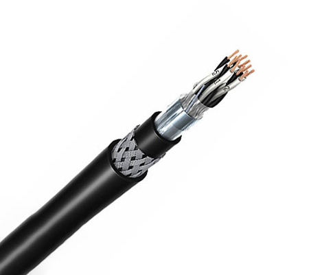
Fire Resistant Instrumentation Cable
Product Overview
The 300/500V Mica+XLPE Insulated Individual and Overall Screened Instrumentation Cables are designed, manufactured, and tested as data transmission cables for emergency services. These cables are used for data and voice transmission when high-frequency signals must be assured even in the event of a fire.
The cables feature plain annealed copper conductors, Mica glass tape with extruded cross-linked XLPE or fire-resistant silicone rubber insulation, individual and overall aluminium/polyester tape screens with tinned copper drain wires, and a thermoplastic LSZH outer sheath. The basic design conforms to BS 5308 / BS 7629-1.
Features & Benefits
-
Fire Resistant: Mica glass tape combined with XLPE or silicone rubber insulation maintains circuit integrity in fire conditions.
-
Individual and Overall Screened: Aluminium/polyester tape screens with tinned copper drain wires minimise crosstalk and electromagnetic interference.
-
LSZH Construction: Thermoplastic LSZH inner and outer sheaths reduce toxic fumes and smoke.
-
Reliable Data Transmission: Insulated cores twisted into pairs with varying lay lengths to minimise crosstalk.
-
Flexible Configuration: Available in 2, 5, 10, and 20 pair configurations with optional armouring.
-
Voltage Rating: 300/500V.
-
Temperature Range: Fixed: -30°C to +70°C; Mobile: -20°C to +50°C.
-
Insulation Resistance: ≥1000 MΩ x km at 20°C.
-
Short Circuit Temperature: XLPE: 250°C; SR: 350°C.
-
Standard Compliant: BS 5308 / BS 7629-1.
-
Sheath Colour: Orange (other colours on request).
Typical Applications
-
Emergency services data transmission
-
Data and voice transmission where high-frequency signal integrity is required during fire
-
Fire alarm systems
-
Emergency lighting systems
-
Control and instrumentation circuits in critical infrastructure
Construction
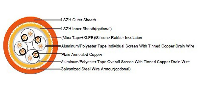
-
Conductor: Plain annealed copper wire, stranded according to IEC(EN) 60228 Class 2
-
Insulation: Mica glass tape covered by extruded cross-linked XLPE compound or fire resistant silicone rubber compound
-
Cabling Elements: Insulated cores are twisted to form pairs with varying lay length to minimise crosstalk. Two-pair cable has four cores laid in quad formation.
-
Cabling: Pairs are cabled together. In cables with 8 pairs or more, 4 pairs are assembled to form a bunch, and the bunches are then cabled together.
-
Individual Screen: Aluminium/polyester tape with 0.5mm² screen (7/0.3mm) tinned copper drain wire
-
Overall Screen: Aluminium/polyester tape with 0.5mm² screen (7/0.3mm) tinned copper drain wire
-
Inner Sheath (Optional): Thermoplastic LSZH compound
-
Armouring (Optional): Galvanized steel wire armour
-
Outer Sheath: Thermoplastic LSZH compound
-
Insulation Colour: White with black numberings
-
Sheath Colour: Orange (other colours on request)
Technical Specifications
Electrical Properties
| Parameter | Value |
|---|---|
| Dielectric Test | 2000 V r.m.s. x 5' (core/core) |
| Insulation Resistance | ≥1000 MΩ x km (at 20°C) |
| Short Circuit Temperature – XLPE | 250°C |
| Short Circuit Temperature – SR | 350°C |
Physical & Thermal Properties
| Parameter | Value |
|---|---|
| Temperature Range – Fixed State | -30°C to +70°C |
| Temperature Range – Mobile State | -20°C to +50°C |
| Minimum Bending Radius – Unarmoured (Silicone Rubber Insulation) | 6 x Overall Diameter |
| Minimum Bending Radius – Unarmoured (XLPE Insulation) | 8 x Overall Diameter |
| Minimum Bending Radius – Armoured | 10 x Overall Diameter |
Construction Parameters – 2 Pairs
| No. of Pairs x Cross Section (mm²) | No./Nominal Diameter of Strands (No./mm) | Nominal Insulation Thickness (mm) | Unarmoured – Nominal Overall Diameter (mm) | Unarmoured – Approx. Weight (kg/km) | Armoured – Diameter Under Armour (mm) | Armoured – Armour Wire Diameter (mm) | Armoured – Nominal Overall Diameter (mm) | Armoured – Approx. Weight (kg/km) |
|---|---|---|---|---|---|---|---|---|
| 2 x 2 x 1.0 | 7/0.43 | 0.6 | 15.2 | 166 | 15.2 | 0.90 | 20.0 | 555 |
| 2 x 2 x 1.5 | 7/0.53 | 0.7 | 17.0 | 205 | 17.0 | 1.25 | 22.7 | 769 |
| 2 x 2 x 2.5 | 7/0.67 | 0.8 | 19.2 | 350 | 19.2 | 1.25 | 24.9 | 938 |
Construction Parameters – 5 Pairs
| No. of Pairs x Cross Section (mm²) | No./Nominal Diameter of Strands (No./mm) | Nominal Insulation Thickness (mm) | Unarmoured – Nominal Overall Diameter (mm) | Unarmoured – Approx. Weight (kg/km) | Armoured – Diameter Under Armour (mm) | Armoured – Armour Wire Diameter (mm) | Armoured – Nominal Overall Diameter (mm) | Armoured – Approx. Weight (kg/km) |
|---|---|---|---|---|---|---|---|---|
| 5 x 2 x 1.0 | 7/0.43 | 0.6 | 17.5 | 335 | 17.5 | 1.25 | 23.2 | 1000 |
| 5 x 2 x 1.5 | 7/0.53 | 0.7 | 21.5 | 433 | 21.5 | 1.60 | 28.1 | 1352 |
| 5 x 2 x 2.5 | 7/0.67 | 0.8 | 24.0 | 592 | 24.0 | 1.60 | 30.8 | 1665 |
Construction Parameters – 10 Pairs
| No. of Pairs x Cross Section (mm²) | No./Nominal Diameter of Strands (No./mm) | Nominal Insulation Thickness (mm) | Unarmoured – Nominal Overall Diameter (mm) | Unarmoured – Approx. Weight (kg/km) | Armoured – Diameter Under Armour (mm) | Armoured – Armour Wire Diameter (mm) | Armoured – Nominal Overall Diameter (mm) | Armoured – Approx. Weight (kg/km) |
|---|---|---|---|---|---|---|---|---|
| 10 x 2 x 1.0 | 7/0.43 | 0.6 | 22.5 | 626 | 22.5 | 1.60 | 29.3 | 1800 |
| 10 x 2 x 1.5 | 7/0.53 | 0.7 | 28.0 | 811 | 28.0 | 1.60 | 35.0 | 2165 |
| 10 x 2 x 2.5 | 7/0.67 | 0.8 | 31.5 | 1132 | 31.5 | 2.00 | 39.5 | 3007 |
Construction Parameters – 20 Pairs
| No. of Pairs x Cross Section (mm²) | No./Nominal Diameter of Strands (No./mm) | Nominal Insulation Thickness (mm) | Unarmoured – Nominal Overall Diameter (mm) | Unarmoured – Approx. Weight (kg/km) | Armoured – Diameter Under Armour (mm) | Armoured – Armour Wire Diameter (mm) | Armoured – Nominal Overall Diameter (mm) | Armoured – Approx. Weight (kg/km) |
|---|---|---|---|---|---|---|---|---|
| 20 x 2 x 1.0 | 7/0.43 | 0.6 | 30.5 | 1143 | 30.5 | 2.00 | 38.5 | 3019 |
| 20 x 2 x 1.5 | 7/0.53 | 0.7 | 38.0 | 1509 | 38.0 | 2.00 | 46.2 | 3684 |
| 20 x 2 x 2.5 | 7/0.67 | 0.8 | 42.5 | 2112 | 42.5 | 2.50 | 51.9 | 5107 |
Note: All values are nominal as provided in the source specification. Actual dimensions and weights may vary within standard manufacturing tolerances. Other conductor sizes and core configurations are available upon request.
Standards & Compliance
The Fire Resistant Instrumentation Cable is designed and tested in accordance with:
-
BS 5308 / BS 7629-1 – Basic design
-
IEC(EN) 60228 Class 2 – Conductor
-
Dielectric Test: 2000 V r.m.s. x 5' (core/core)
Ordering Information
To request a quote or place an order, please provide the following information:
-
Product Type: Fire Resistant Instrumentation Cable
-
Voltage Rating: 300/500V
-
Number of Pairs and Cross-Section: e.g., 2 x 2 x 1.0 mm², 10 x 2 x 1.5 mm², 20 x 2 x 2.5 mm²
-
Insulation: Mica + XLPE or Mica + Silicone Rubber
-
Individual Screen: Yes
-
Overall Screen: Yes
-
Inner Sheath: Optional (Yes/No)
-
Armouring: Optional (Yes/No)
-
Sheath Colour: Orange (standard) or other on request
-
Quantity: Total length in meters