
N2XSY 6/10kV Medium Voltage Cables
Product Overview:
Engineered for reliable power distribution in demanding industrial environments, the N2XSY 6/10kV cable delivers superior performance under DIN VDE 0276-620, HD 620, and EN 60228 standards. Featuring XLPE insulation, copper screening, and flame-retardant PVC sheath, this cable is designed for direct burial, duct installation, and industrial plant applications where safety and durability are critical.
Key Features & Benefits
-
Robust Construction: XLPE insulation + dual semi-conductive layers ensure electrical integrity
-
Flame Retardancy: Complies with IEC/EN 60332-1-2 for enhanced fire safety
-
Wide Temp Range: -20°C to +70°C (operational), -5°C to +70°C (flexed)
-
Short-Circuit Resilience: Withstands 250°C conductor temperatures (1-sec fault)
-
Easy Installation: 15×OD bending radius for confined spaces
-
Certified Reliability: CE and ISO 9001 certified
Technical Specifications
| Parameter | Specification | Standard |
|---|---|---|
| Rated Voltage | 6/10kV (Um=12kV) | DIN VDE 0276-620 |
| Test Voltage | 21 kV AC | EN 60228 |
| Conductor | Compacted copper (Class 2) | IEC 60228 |
| Insulation | XLPE (Cross-Linked Polyethylene) | HD 620 |
| Screen | Copper wires + copper tape wrapping | IEC 60502-2 |
| Sheath | PVC (Red) / HDPE (optional) | IEC 60332-1-2 |
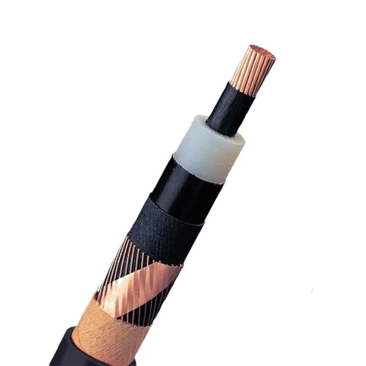
Construction Details
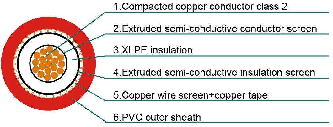
Layer-by-Layer Structure:
-
Conductor: Stranded, compacted copper (Class 2 per IEC 60228)
-
Conductor Screen: Extruded semi-conductive compound
-
Insulation: XLPE for thermal stability (90°C continuous)
-
Insulation Screen: Cold-strippable semi-conductive layer
-
Metallic Screen: Copper wire braid + helical copper tape
-
Outer Sheath: Flame-retardant PVC (standard red)
Technical Data Table (6/10kV Configuration)
| Cross Section [mm²] | Insul. Thick. [mm] | Screen [mm²] | Sheath Thick. [mm] | Min. OD [mm] | Max. OD [mm] | Weight [kg/km] | Buried Current [A]* | Air Current† [A] |
|---|---|---|---|---|---|---|---|---|
| 35 | 3.4 | 16 | 2.5 | 23.0 | 28.0 | 900 | 187 | 197 |
| 50 | 3.4 | 16 | 2.5 | 24.0 | 29.0 | 1050 | 220 | 236 |
| 70 | 3.4 | 16 | 2.5 | 26.0 | 31.0 | 1300 | 268 | 294 |
| 95 | 3.4 | 16 | 2.5 | 26.0 | 32.0 | 1600 | 320 | 358 |
| 120 | 3.4 | 16 | 2.5 | 28.0 | 34.0 | 1850 | 363 | 413 |
| 150 | 3.4 | 25 | 2.5 | 29.0 | 35.0 | 2200 | 405 | 468 |
* Buried current rating: Direct burial in ground at 20°C soil temperature, trefoil formation
† Air current rating: Laid in air at 30°C ambient, trefoil formation
Application Scenarios
-
Power Distribution Networks: Substation connections, grid feeders
-
Industrial Plants: Motor feeds, conveyor systems, heavy machinery
-
Renewable Energy: Wind turbine inter-array cabling
-
Infrastructure: Underground ducts, tunnels, cable trays
-
Hazardous Areas: Chemical plants, refineries (flame-retardant design)
Engineering Selection Guide
| Selection Factor | Technical Guidance |
|---|---|
| Current Capacity | 150mm² supports 468A in air (30°C trefoil) |
| Mechanical Protection | 2.5mm PVC sheath + copper screen for impact zones |
| Voltage Drop | ≤3% with 95mm² @ 200m run (400V system) |
| Environmental Exposure | Use HDPE sheath alternative for UV/abrasion zones |
Certifications & Packaging
-
Standards: DIN VDE 0276-620, HD 620, EN 60228, IEC/EN 60332-1-2
-
Certifications: CE, ISO 9001
-
Packaging: Fumigated steel-wood drums (1,000m/2,000m lengths)
-
Customization: Sheath color (red standard), HDPE option available