
Product Overview
This 0.6/1kV XLPE insulated and PVC sheathed unarmored cable features two power cores plus an earth conductor (2C+E). Designed for mains, submains, and subcircuits in buildings and industrial plants, it is suitable for installation unenclosed, in conduit, direct buried, or in underground ducts where mechanical damage is not expected. Manufactured to AS/NZS 5000.1 and related standards, the XLPE insulation provides enhanced thermal performance and higher current-carrying capacity compared to PVC-insulated alternatives.
Applications
-
Mains, submains, and subcircuits in buildings
-
Industrial plants and commercial installations
-
Installation in conduit, direct burial, or underground ducts
-
Locations not subject to mechanical damage
Standards
-
AS/NZS 5000.1
-
AS/NZS 3008
-
AS/NZS 1125
-
IEC 60502-1
Specifications at a Glance
| Property | Detail |
|---|---|
| Voltage rating | 0.6/1 kV |
| Conductor | Plain annealed copper |
| Insulation | XLPE X-90 |
| Insulation colours | Red, Black (cores) + Green/Yellow (earth) |
| Sheath | PVC 5V-90 |
| Sheath colour | Black (other colours available on request) |
| Armour | None (unarmored) |
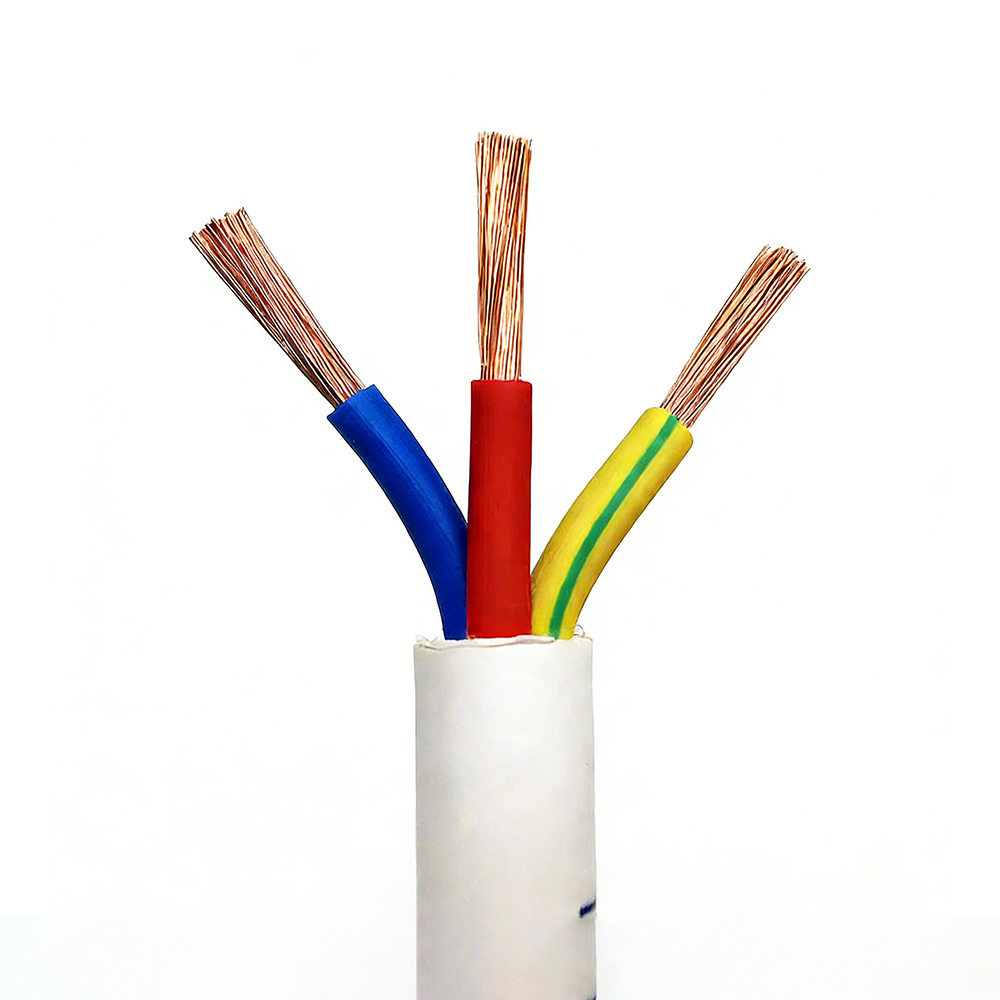
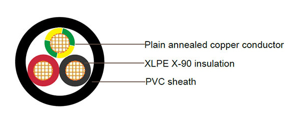
Cable Construction
-
Conductor
Plain annealed copper, circular stranded. -
Insulation
Cross-Linked Polyethylene (XLPE) type X-90.
Colour coding: Red, Black for two cores; Green/Yellow for earth. -
Assembly
Two insulated cores + one insulated earth conductor laid up together. -
Outer sheath
Polyvinylchloride (PVC) compound type 5V-90.
Colour: Black (custom colours available).
Technical Parameters
Table 1 – Electrical Characteristics & Current Ratings
| Nominal Area (mm²) | Current Rating – Unenclosed in Air (A) | Current Rating – Buried Direct (A) | Current Rating – Buried in Ducts (A) | Max. DC Resistance @20 °C (Ω/km) | Max. AC Resistance @90 °C (Ω/km) | Reactance (Ω/km) | Single‑Phase Voltage Drop @90 °C (mV/A/m) |
|---|---|---|---|---|---|---|---|
| 10 | 80 | 107 | 82 | 1.83 | 2.33 | 0.084 | 1.68 |
| 16 | 107 | 139 | 107 | 1.51 | 1.47 | 0.081 | 2.95 |
| 25 | 143 | 182 | 139 | 0.727 | 0.927 | 0.081 | 1.86 |
| 35 | 160 | 130 | 160 | 0.524 | 0.669 | 0.0786 | 1.35 |
| 50 | 195 | 160 | 190 | 0.387 | 0.494 | 0.0751 | 1.00 |
| 70 | 250 | 200 | 235 | 0.268 | 0.343 | 0.0741 | 0.703 |
| 95 | 310 | 240 | 285 | 0.193 | 0.248 | 0.0725 | 0.520 |
| 120 | 360 | 285 | 325 | 0.153 | 0.197 | 0.0713 | 0.423 |
Table 2 – Construction Details
| Nominal Conductor Area (mm²) | Conductor No./Diameter (no./mm) | Nom. Insulation Thickness (mm) | Nom. Earth Conductor Area (mm²) | Nom. Earth Insulation Thickness (mm) | Nom. Sheath Thickness (mm) | Nom. Overall Diameter (mm) | Approx. Mass (kg/km) |
|---|---|---|---|---|---|---|---|
| 10 | 7/1.35 | 0.7 | 4 | 0.7 | 1.4 | 14.9 | 380 |
| 16 | 7/1.70 | 0.7 | 6 | 0.7 | 1.4 | 16.6 | 520 |
| 25 | 7/2.14 | 0.9 | 6 | 0.7 | 1.4 | 20.2 | 750 |
| 35 | 7/2.65 | 0.9 | 10 | 0.7 | 1.4 | 23.0 | 985 |
| 50 | 19/1.89 | 1.0 | 16 | 0.7 | 1.4 | 24.1 | 1310 |
| 70 | 19/2.24 | 1.1 | 25 | 0.9 | 1.4 | 29.8 | 1860 |
| 95 | 19/2.65 | 1.1 | 25 | 0.9 | 1.5 | 31.6 | 2415 |
| 120 | 19/2.94 | 1.2 | 35 | 0.9 | 1.6 | 35.5 | 3055 |
Note: All values are nominal and subject to standard tolerances.