
MC-HL Armored Cable 3 Conductors EPR PVC MC-HL/MV-105 5kV-133% 8kV-100% - UL 1072
Product Overview
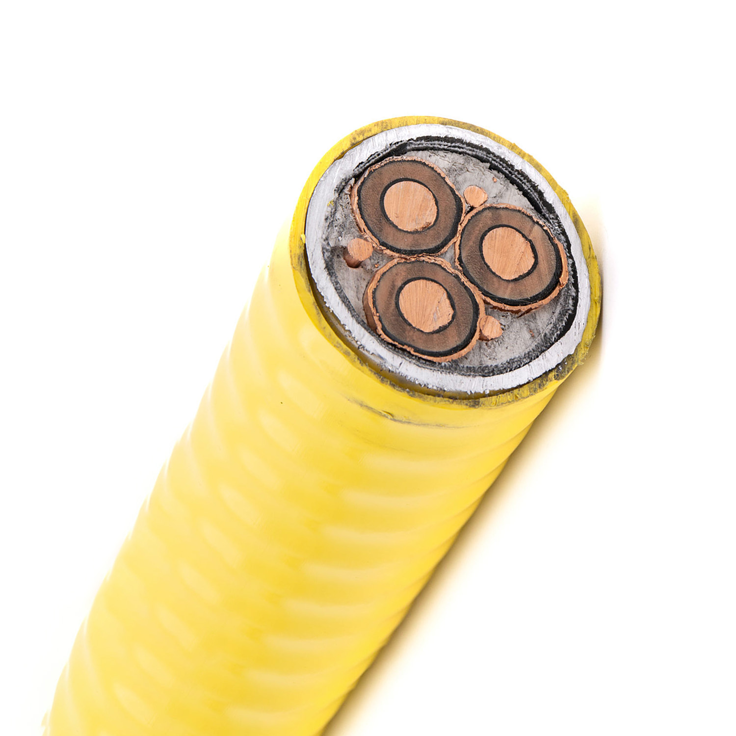
The MC-HL/MV-105 is a robust 3-conductor, armored medium-voltage power cable designed for the most demanding industrial applications. Featuring EPR insulation, an impervious aluminum armor, and three integral grounding conductors, it is the preferred wiring solution for Variable Frequency Drives (VFDs) and installations in hazardous locations. Rated for 5kV-133% and 8kV-100% systems, it combines superior electrical performance with exceptional mechanical and environmental protection.
Key Features & Benefits
-
VFD & Hazardous Location Ready: Specifically engineered for pulse-width modulated (PWM) inverter drives and approved for use in Class I, II, III Div. 1 & 2 and Zone 1 & 2 hazardous areas per NEC.
-
Superior Electrical Performance: EPR insulation provides outstanding corona resistance, high dielectric strength, and electrical stability under thermal and mechanical stress.
-
Maximum Environmental Protection: The continuously welded, corrugated aluminum armor acts as an impervious barrier against moisture, gases, and liquids. The sunlight-resistant PVC jacket is rated for -40°C cold impact.
-
Enhanced Safety Design: Includes three symmetrical grounding conductors and meets stringent flame retardancy tests (FT4, IEEE 383, ICEA T-29-520).
Applications
-
Primary Application: Power supply wiring for AC motors controlled by Variable Frequency Drives (VFDs/PWM inverters).
-
Installation Locations: Suitable for use in hazardous locations, cable trays, raceways, direct burial, embedded in concrete, and in wet/dry areas. Ideal for industrial power distribution feeders and branch circuits.
-
Industries: Widely used in industrial plants, manufacturing facilities, and is UL Listed for Marine Shipboard service with ABS approval.
Specifications & Ratings
-
Voltage Rating: 5kV (133% insulation level) / 8kV (100% insulation level)
-
Temperature Rating: 105°C conductor temperature (MV-105); -40°C minimum installation/bending temperature.
-
Standards: UL Types MC-HL and MV-105.
-
Conductor Size Range: 6 AWG through 1000 kcmil.
-
Flame Retardancy: Complies with FT4, IEEE 383, IEEE 1202, ICEA T-29-520.
Construction Details
| Layer | Component | Material / Specification |
|---|---|---|
| 1. Conductor | Phase Conductors | Bare, annealed copper, compact stranded per ASTM B496 (6 AWG - 1000 kcmil) |
| 2. Strand Shield | Extruded Strand Shield (ESS) | Thermoset semi-conductive layer per ICEA S-93-639 & UL 1072 |
| 3. Insulation | Insulation | 115 mil Ethylene Propylene Rubber (EPR) per ICEA S-93-639 & UL 1072 |
| 4. Insulation Shield | Extruded Insulation Shield (EIS) | Thermoset semi-conductive, strippable layer |
| 5. Metallic Shield | Shield | 5 mil bare copper tape with 25% overlap |
| 6. Grounding | Grounding Conductors | Three (3) bare copper, Class B stranded, sized per UL 1072 & NEC 250 |
| 7. Armor | Armor | Continuously welded, corrugated Aluminum Alloy sheath (UL 1072/1569) |
| 8. Jacket | Outer Jacket | Flame-retardant, sunlight-resistant PVC, Yellow. Meets -40°C brittleness test (ASTM D746). |
Compliance & Standards
-
Safety & Listing: UL Type MC-HL, UL Type MV-105, UL 1072, UL 1569, UL 2225, UL 1309 (Marine), CSA C68.3, ABS approval.
-
Design & Material: ICEA S-93-639, AEIC CS8, UL 1072.
-
Flame & Fire Tests: ICEA T-29-520, IEEE 383, CSA FT4, IEEE 1202, IEC 60332-3 Cat. A.
-
Conductor Standards: ASTM B3, ASTM B496.