
Product Overview
-
Colour coded fibers and binders for quick and easy identification during installation.
-
Compact design results in excellent sag‑tension performance of the cable.
-
Aluminium‑clad steel wires and aluminium alloy wires provide mechanical strength to withstand installation and operating conditions, while achieving conductivity required to control temperature rise during short‑circuit fault conditions.
-
Optical unit placed inside the aluminium tube provides exceptional mechanical and thermal protection for the fiber against severe environments and external lateral force.
-
Thick‑walled aluminium tubes provide hermetic seal for optical units, offering excellent crush resistance and low resistivity.
-
Unique design has maximum allowable tension to control fiber strain.
-
Stranded wires used for optimising the mechanical and electrical properties of the cables.
-
High load, long span capability.
Application
OPGW is a dual functioning cable performing the duties of a ground wire and also providing a path for the transmission of voice, video or data signals. The fibers are protected from environmental conditions (lightning, short circuit, loading) to ensure reliability and longevity. The cable is designed to be installed on transmission and distribution lines to carry voice, data and video communications, especially in lightning waveform monitoring systems, observation systems for overhead test lines, maintenance data information systems, power line protection systems, power line operation systems, and unmanned substation monitoring.
OPGW cable has two constructions:
-
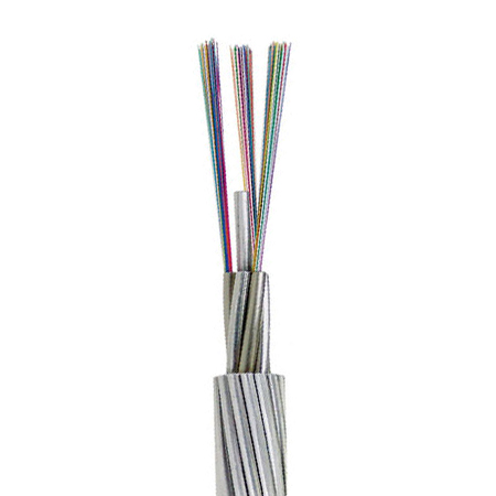
Central loose tube type – The fibers are placed loosely in a sealed and water‑resistant stainless steel tube filled with water blocking gel. This tube provides protection to the fibers during installation and operation under severe environmental conditions. An aluminium layer over the tube is optional. The stainless steel optical tube is located at the center of the cable protected by single or multiple layers of aluminium‑clad steel and aluminium alloy wires. The aluminium‑clad steel wires are shaped trapezoidally around the optical unit to provide compact construction. This type can accommodate up to 48 fibers in a cable. Each optical fiber is clearly distinguishable using a fiber identification system consisting of coloring and ring marks. This compact design features high mechanical strength and fault current rating within a smaller diameter, resulting in excellent sag‑tension performance.
-
Multi loose tube type – Two or three stainless steel optical tubes are helically stranded in the inner layer of a multiple‑layer cable. Designed mostly for very high fiber count requirements over 48, with the maximum fiber count reaching 144. The multi loose tube type can meet the requirements of huge cross‑section and large current capacity.
Approvals
-
Telcordia GR‑20
-
RUS 7 CFR 1755.900 (REA PE‑90)
-
ICEA S 87‑640
-
IEEE 1222
Technical Data
| Property | Value |
|---|---|
| Temperature range during installation | -40°C to +70°C |
| Temperature range fixed installed | -30°C to +60°C |
| Minimum bending radius (unarmoured) | 10 × OD |
| Minimum bending radius (armoured) | 20 × OD |
| Tensile strength at installation (unarmoured) | 4000 N |
| Tensile strength at installation (armoured) | 6000 N |
| Short‑term tensile strength | 1500 N (several days) |
| Constant tensile strength | 750 N |
Specifications
| Property | Details |
|---|---|
| Working Temperature | 70°C |
| Cold Resistant | -40°C |
| Oil Resistance | ✓ |
| Construction | Central loose tube or multi loose tube |
| Metallic protection | Aluminium tube / stainless steel tube + Al‑clad steel & Al alloy wires |
Construction (General)
-
Fiber: 2–24 fibers (diameter 250 μm) with coloured primary coating (expandable up to 144 fibers in multi‑tube design)
-
Loose tube: Stainless steel or aluminium, jelly‑filled, hermetically sealed
-
Central strength member / optical unit placement: Central or stranded layers
-
Metallic wires: Aluminium‑clad steel wires (trapezoidal or round) and aluminium alloy wires
-
Water blocking: Gel filling + optional water‑swellable elements
Technical Parameters – OPGW Mechanical & Electrical Properties
Mechanical Properties & Fiber Compliant Data
| Cable Section (mm²) | Nominal Outer Diameter (mm/in) | Nominal Weight (kg/km) / (lb/kft) | Max Working Tension (kN) | Modulus of Elasticity (kN/mm²) | Heat Expansion Coefficient (10⁻⁶/°C) | DC Resistance (Ω/km) | Short‑Circuit Current Capacity (kA²s) |
|---|---|---|---|---|---|---|---|
| 35 | 8.1 / 0.318 | 250 / 167.79 | 45.2 | 162.0 | 13.0 | 2.433 | 8.9 |
| 50 | 9.6 / 0.378 | 343 / 230.20 | 63.0 | 162.0 | 13.0 | 1.743 | 16.5 |
| 70 | 11.4 / 0.448 | 487 / 326.85 | 89.3 | 162.0 | 13.0 | 1.237 | 3.04 |
| 90 | 12.5 / 0.492 | 368 / 246.98 | 58.2 | 94.1 | 17.3 | 0.473 | 72.7 |
| 105 | 13.5 / 0.531 | 428 / 287.25 | 67.9 | 94.1 | 17.3 | 0.403 | 98.8 |
| 130 | 15.0 / 0.590 | 527 / 353.69 | 83.8 | 94.1 | 17.3 | 0.329 | 149.9 |
Application notes (by layer design):
| Design | Effective Sectional Area (mm²) | Suitable Rated Voltages |
|---|---|---|
| Single‑layer | 50 – 83 | 66 kV, 115 kV, 150 kV, 250 kV, 275 kV |
| Double‑layer | 90 – 200 | 150 kV, 250 kV, 275 kV, 380 kV, 500 kV |
| Three‑layer | 200 – 400 | 380 kV, 420 kV, 500 kV (European markets) |
Mechanical Properties Summary
| Property | Unarmoured | Armoured |
|---|---|---|
| Minimum bending radius under installation | 20 × OD | 20 × OD |
| Minimum bending radius during operation | 10 × OD | 20 × OD |
| Maximum compressive load | 4000 N | 6000 N |
| Repeated impact | 4.4 N·m (J) | 4.4 N·m (J) |
| Twist (torsion) | 180° × 10 times, 125×OD | 180° × 10 times, 125×OD |
| Cyclic flexing | 100 cycles | 25 cycles |
| Crush resistance | 220 N/cm (125 lb/in) | 220 N/cm (125 lb/in) |
| Operating temperature range | -40°C to +70°C | -40°C to +70°C |
| Storage temperature range | -50°C to +70°C | -50°C to +70°C |
Test Methods (IEC 60794-1-2)
| Test | Standard |
|---|---|
| Temperature Cycling | F2 |
| Tensile Strength | E1A |
| Crush | E3 |
| Impact | E4 |
| Repeated Bending | E6 |
| Torsion | E7 |
| Kink | E10 |
| Cable Bend | E11 |
| Cold Bend | E11 |