
Product Overview
High capacity cable offering great flexibility for placement on overhead transmission towers, eliminating the need for a support messenger.
-
Dry core design and high tension strength capability suitable for toughest environmental and electrical conditions.
-
Fit for extra high voltage power lines without interruption of power service to customers.
-
Typical spans with 1%‑1.5% installation sag environment.
Application
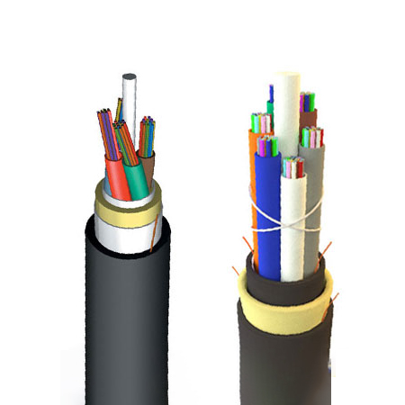
The "All Dielectric Self‑supporting (ADSS)" cable is designed for aerial self supporting application at short, medium and long span distances. ADSS cable offers a rapid and economical means for deployment by cable television operators, telephone companies and power utilities. It is adopted for high voltage, middle, small span conditions in Power Transmission System or mazy terrain such as river spanning, mountains.
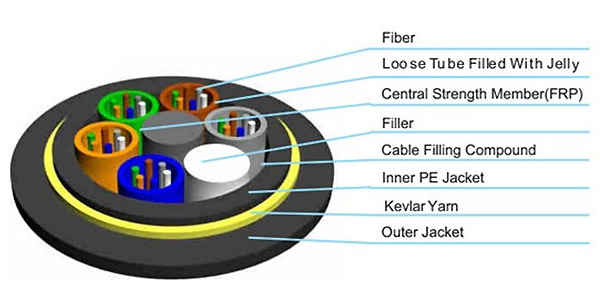
The cable consists of 5 to 36 fibers containing tubes or fillers stranded in up to 3 layers around a central strength member and bound under a PE jacket. Each tube contains 6‑12 fibers. All the fibers in the cores are filled with water blocking gel. Fillers may be used to preserve the cable geometry. A water swelling tape is helically wrapped around the cable core. Aramid yarns are helically laid to supply peripheral strengthening of the cable. The outer jacket is tightly bounded over the aramid yarn layer. The cable jacket incorporates an optional inner polyethylene jacket and an outer polyethylene or AT (anti‑tracking) jacket. When the induction on cable surface is above 12 kV, anti‑tracking sheath material (AT) will be applied. With AT outer jacket, the maximum electric field strength at operating point can reach 35 kV. For long span application, a double jacket design can be considered. An optional ripcord can be put under the jacket layer to facilitate its removal.
Approvals
-
Telcordia GR‑20
-
RUS 7 CFR 1755.900 (REA PE‑90)
-
ICEA S 87‑640
-
IEEE 1222
Technical Data
| Property | Value |
|---|---|
| Temperature range during installation | -40°C to +70°C |
| Temperature range fixed installed | -30°C to +60°C |
| Minimum bending radius (unarmoured) | 10×OD |
| Minimum bending radius (armoured) | 20×OD |
| Tensile strength at installation (unarmoured) | 4000 N |
| Tensile strength at installation (armoured) | 6000 N |
| Short‑term tensile strength | 1500 N (several days) |
| Constant tensile strength | 750 N |
| Resistance to pressure | 200 N / 100 mm |
Specifications
| Property | Details |
|---|---|
| Working Temperature | 70°C |
| Cold Resistant | -40°C |
| Construction | Loose tube, central strength member, aramid yarns |
| Sheath Options | PE or AT (anti‑tracking) |
Construction
-
Fiber: 5 to 36 fibers (diameter 250 μm) with coloured primary coating. Each loose tube contains 6‑12 fibers.
-
Loose tube: Elastomer, jelly‑filled. Tubes or fillers stranded in up to 3 layers around a central strength member.
-
Central strength member: Provides core reinforcement.
-
Water blocking: Water swelling tape helically wrapped around the cable core.
-
Peripheral strengthening: Aramid yarns helically laid.
-
Jacket: Tightly bonded over aramid yarns. Optional inner PE jacket and outer PE or AT (anti‑tracking) jacket. AT sheath used when surface induction >12 kV (max field strength 35 kV). Double jacket for long spans.
-
Ripcord (optional): Under jacket layer for easy removal.
Technical Parameters – Physical & Mechanical Properties
Span Performance (with different ice/wind conditions)
| Span (m) | Ice+Wind: 0mm + 35 m/s | Ice+Wind: 12mm + 30 m/s | ||||||
|---|---|---|---|---|---|---|---|---|
| Cable O.D. (mm/in) | Cable Weight (kg/km)/(lb/kft) | Max Working Tension (N/lb) | Max Sag (%) | Cable O.D. (mm/in) | Cable Weight (kg/km)/(lb/kft) | Max Working Tension (N/lb) | Max Sag (%) | |
| 100 | 13.9 / 0.547 | 152 / 102.0 | 7578 / 1704 | 2 | 13.8 / 0.543 | 150 / 100.7 | 6621 / 1489 | 2 |
| 200 | 14.3 / 0.563 | 161 / 108.1 | 10430 / 2346 | 3 | 14.1 / 0.555 | 157 / 105.4 | 9000 / 2024 | 3 |
| 400 | 15.9 / 0.626 | 199 / 133.6 | 23221 / 5223 | 3 | 15.4 / 0.606 | 187 / 125.5 | 19225 / 4331 | 3 |
| 500 | 16.7 / 0.657 | 220 / 147.7 | 30590 / 6881 | 3 | 16.1 / 0.634 | 204 / 136.9 | 24885 / 5598 | 3 |
| 600 | 16.3 / 0.642 | 209 / 140.3 | 26952 / 6063 | 4 | 15.7 / 0.618 | 196 / 131.5 | 22154 / 4983 | 4 |
| 800 | 16.5 / 0.650 | 216 / 145.0 | 29452 / 6625 | 5 | 15.9 / 0.626 | 201 / 134.9 | 24042 / 5408 | 6 |
| 1000 | 16.7 / 0.657 | 221 / 148.3 | 31271 / 7034 | 6 | 16.1 / 0.634 | 204 / 136.9 | 24407 / 5490 | 6 |
Above table does not cover all available types. Other ADSS cables can be manufactured upon customer's request according to different span and sag environments.
Mechanical Properties Summary
| Property | Value |
|---|---|
| Minimum bending radius under installation | 20 × OD |
| Minimum bending radius during operation (unarmoured) | 10 × OD |
| Minimum bending radius during operation (armoured) | 20 × OD |
| Maximum compressive load | 4000 N |
| Repeated impact | 4.4 N·m (J) |
| Twist (torsion) | 180° × 10 times, 125×OD |
| Cyclic flexing | 100 cycles |
| Crush resistance | 263 N/cm (1250 lb/in) |
| Operating temperature range | -40°C to +70°C |
| Storage temperature range | -50°C to +70°C |