
1. Product Overview
Submersible Oil Pump Cables deliver critical power and control to Electric Submersible Pumps (ESPs) in oil wells, enabling efficient extraction of crude oil from deep reservoirs. Engineered for extreme downhole conditions, these cables withstand high temperatures, corrosive fluids, crushing pressures, and mechanical stress to ensure uninterrupted operation.
2. Compliance & Standards
-
API RP 11S5: Application of ESP Cable Systems
-
API RP 11S6: Testing of ESP Cable Systems
-
IEEE 1018: Specification Standard for ESP Cables
-
Certified for hazardous environments (oil/gas reservoirs).
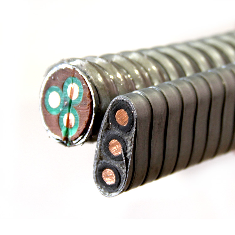
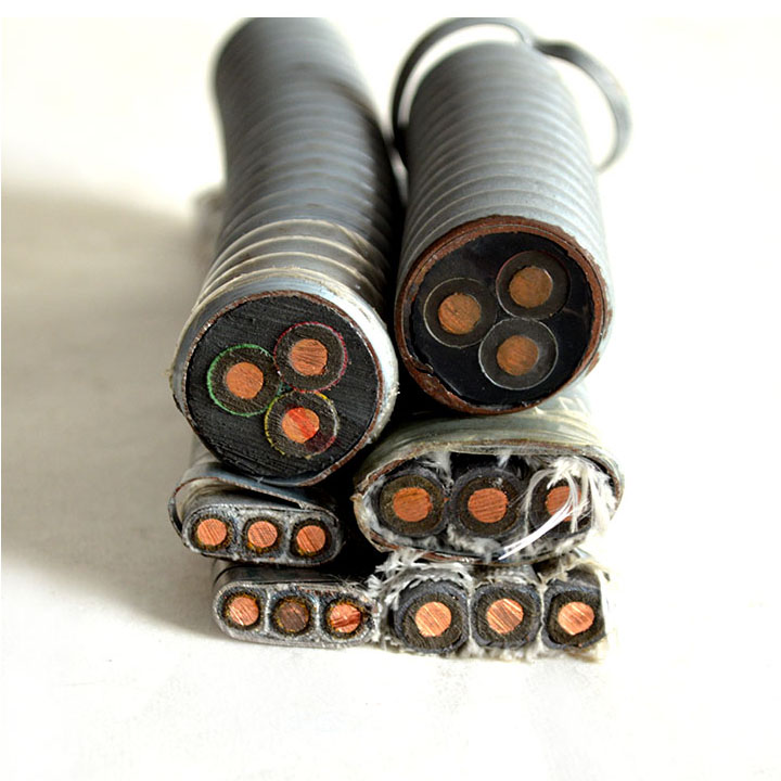
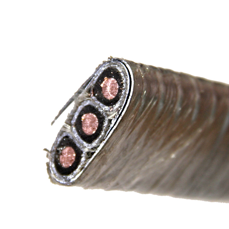
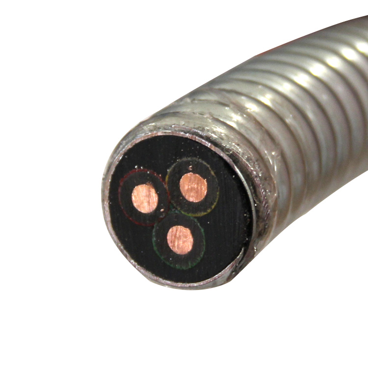
3. Construction & Materials
| Component | Specification |
|---|---|
| Type | Flat: Space-optimized for narrow wellbores. Round: Superior crush resistance. |
| Conductor | Solid Electrolytic Copper (Uncoated), AWG 6 to 1 (13.3–42.4 mm²). High conductivity & flexibility. |
| Insulation | EPR/EPDM Rubber: 90°C–150°C operating temperature. Resists oil, H₂S, acids, and moisture. |
| Barrier Sheath | Lead Alloy: Impermeable seal against gas/oil ingress and corrosive fluids. |
| Armor | Galvanized Steel Wire: Crush/abrasion protection. Flat: Tape armor. Round: Wire armor. |
| Outer Sheath | NBR/EPDM: Oil-resistant, abrasion-proof jacket (over armor for round cables). |
| Cores | 3-Core configuration (3-phase power). |
4. Key Features
-
High-Temperature Resilience: Continuous operation at 90°C–150°C.
-
Chemical Resistance: Immune to crude oil, brine, H₂S, CO₂, and well treatment chemicals.
-
Mechanical Durability: Steel armor protects against crushing, fishbite, and installation stress.
-
Fluid Barrier: Lead sheath prevents dielectric breakdown from fluid penetration.
-
Voltage Ratings: 3 kV or 5 kV options (thicker insulation for higher voltage).
5. Application Scenarios
-
Powering ESPs in onshore/offshore oil production wells.
-
Vertical, deviated, or horizontal wellbores.
-
Reservoirs with exposure to:
-
Crude oil, brine, natural gas
-
H₂S, CO₂, high pressure (>5,000 psi)
-
Temperatures up to 150°C.
-
6. Technical Specifications
6.1 Flat Cables
 A. 3 kV Flat Cable (EPDM Insulation + Lead Sheath)
| AWG | Area (mm²) | Insul. Thick (mm) | Lead Thick (mm) | Finished Thick (mm) | Width (mm) | Weight (kg/km) |
|---|---|---|---|---|---|---|
| 6 | 13.3 | 1.7 | 0.76 | 13.1 | 35.7 | 1,700 |
| 4 | 21.1 | 1.7 | 0.76 | 14.2 | 35.9 | 2,100 |
| 2 | 33.6 | 1.7 | 0.76 | 15.6 | 40.0 | 2,600 |
| 1 | 42.4 | 1.7 | 0.76 | 16.4 | 42.4 | 3,000 |
B. 5 kV Flat Cable (Enhanced Insulation)
| AWG | Area (mm²) | Insul. Thick (mm) | Lead Thick (mm) | Finished Thick (mm) | Width (mm) | Weight (kg/km) |
|---|---|---|---|---|---|---|
| 6 | 13.3 | 1.9 | 0.76 | 12.5 | 34.0 | 1,850 |
| 4 | 21.1 | 1.9 | 0.76 | 14.6 | 37.1 | 2,230 |
| 2 | 33.6 | 1.9 | 0.76 | 16.0 | 41.0 | 2,770 |
| 1 | 42.4 | 1.9 | 0.76 | 16.8 | 43.6 | 3,140 |
6.2 Round Cables
A. 3 kV Round Cable (Lead Sheath + EPDM Outer)
| AWG | Area (mm²) | Insul. Thick (mm) | Lead Thick (mm) | EPDM Thick (mm) | OD (mm) | Weight (kg/km) |
|---|---|---|---|---|---|---|
| 6 | 13.3 | 1.7 | 0.75 | 1.52 | 28.6 | 2,030 |
| 4 | 21.1 | 1.7 | 0.75 | 1.52 | 30.9 | 2,440 |
| 2 | 33.6 | 1.7 | 0.75 | 1.52 | 33.8 | 3,020 |
| 1 | 42.4 | 1.7 | 0.75 | 1.52 | 35.6 | 3,400 |
B. 5 kV Round Cable (Enhanced Insulation)
| AWG | Area (mm²) | Insul. Thick (mm) | Lead Thick (mm) | EPDM Thick (mm) | OD (mm) | Weight (kg/km) |
|---|---|---|---|---|---|---|
| 6 | 13.3 | 1.9 | 0.75 | 1.52 | 30.5 | 2,120 |
| 4 | 21.1 | 1.9 | 0.75 | 1.52 | 32.8 | 2,590 |
| 2 | 33.6 | 1.9 | 0.75 | 1.52 | 35.7 | 3,110 |
| 1 | 42.4 | 1.9 | 0.75 | 1.52 | 37.4 | 3,500 |
Notes:
EPDM Outer Sheath: Serves as armor bedding/protection in round cables.
Weight: Metric standardized to kg/km (not kg/m).
Conductor: Solid uncoated copper per ASTM B3.
7. Ordering Information
Specify:
-
Cable Type (Flat/Round)
-
Voltage Rating (3 kV/5 kV)
-
Conductor Size (AWG or mm²)
-
Length
-
Special Requirements (e.g., H₂S resistance >500 ppm).