
Product Overview
Aluminum wire armored (AWA) cable is widely used for industrial wiring and mains power distribution. It can be installed directly in the ground, in ducts, clipped to surfaces, on cable trays, in free air, or embedded in concrete. This cable offers excellent mechanical protection and corrosion resistance for demanding environments.
Standards:
-
China National Standard (GB/T)
-
BS, DIN, IEC, or as per customer requirements
Key Characteristics
-
Conductor continuous operating temperature:
-
XLPE insulated: 90°C
-
PVC insulated: 70°C (available on request)
-
-
Minimum ambient temperature during laying: 0°C
-
Minimum bending radius during installation:
-
Unarmored cable: ≥ 6 × overall diameter
-
Armored or copper tape screened cable: ≥ 12 × overall diameter
-
Flexible screened cable: ≥ 6 × overall diameter
-
Specifications
| Property | Details |
|---|---|
| Voltage Level | Low Voltage |
| Conductor Material | Aluminum |
| Insulation | XLPE (Cross-linked Polyethylene) |
| Sheath | PVC |
| Filler | Suitable filler material |
| Armor Type | Steel Wire Armor (AWA) |
Optional features available on request:
Fire-retardant, flame-resisting, low-halogen, low-smoke, halogen-free, acid & alkali resistant
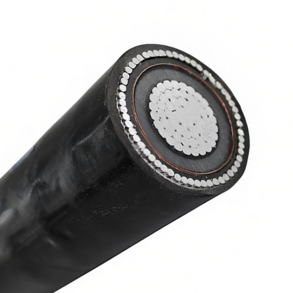
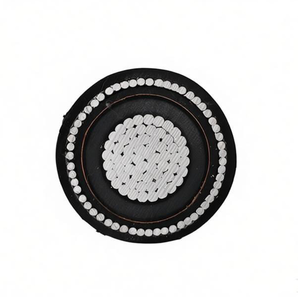
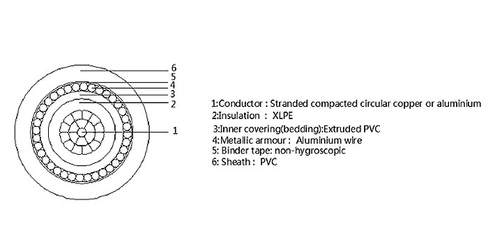
Construction
-
Conductor (Aluminum, compacted stranded or solid)
-
XLPE Insulation
-
Filler (suitable material)
-
PVC Sheath
-
Steel Wire Armor (AWA)
Technical Parameters
YJV72 / YJLV72 – Single Core Aluminum Conductor, XLPE Insulated, Steel Wire Armored, PVC Sheathed
Notes:
-
RE = Circular Solid Conductor
-
CC = Compacted Circular Stranded Conductor
-
SM = Sector Shaped Stranded Conductor (not shown in this table)
-
YJV72 = Copper conductor version (not listed)
-
YJLV72 = Aluminum conductor version (data below)
| Type | Specification (mm²) | Conductor Outer Diameter (mm) | Nominal Insulation Thickness (mm) | Aluminum Wire Diameter (mm) | Nominal Sheath Thickness (mm) | Approx. Cable Outer Diameter (mm) | Approx. Weight (Cu) (kg/km) | Approx. Weight (Al) (kg/km) | Ampacity in Air (A) – Cu | Ampacity in Air (A) – Al | Ampacity in Soil (A) – Cu | Ampacity in Soil (A) – Al |
|---|---|---|---|---|---|---|---|---|---|---|---|---|
| YJLV72 | 1×4 RE | 2.24 | 0.7 | 1.25 | 1.8 | 16.9 | 228 | 204 | 45 | 35 | 60 | 50 |
| YJLV72 | 1×6 RE | 2.76 | 0.7 | 1.25 | 1.8 | 16.9 | 258 | 222 | 55 | 45 | 70 | 50 |
| YJLV72 | 1×10 CC | 3.8 | 0.7 | 1.25 | 1.8 | 16.9 | 321 | 261 | 75 | 60 | 95 | 75 |
| YJLV72 | 1×16 CC | 4.8 | 0.7 | 1.25 | 1.8 | 17.0 | 357 | 255 | 100 | 80 | 125 | 100 |
| YJLV72 | 1×25 CC | 6.0 | 0.9 | 1.25 | 1.8 | 17.4 | 482 | 323 | 140 | 115 | 160 | 130 |
| YJLV72 | 1×35 CC | 7.0 | 0.9 | 1.25 | 1.8 | 18.4 | 597 | 375 | 175 | 140 | 190 | 150 |
| YJLV72 | 1×50 CC | 8.4 | 1.0 | 1.6 | 1.8 | 19.6 | 788 | 487 | 210 | 170 | 225 | 180 |
| YJLV72 | 1×70 CC | 10.0 | 1.1 | 1.6 | 1.8 | 21.5 | 1032 | 598 | 270 | 215 | 280 | 225 |
| YJLV72 | 1×95 CC | 11.5 | 1.1 | 1.6 | 1.8 | 23.1 | 1319 | 718 | 340 | 275 | 335 | 270 |
| YJLV72 | 1×120 CC | 13.0 | 1.2 | 2.0 | 1.8 | 24.7 | 1657 | 892 | 400 | 320 | 380 | 305 |
| YJLV72 | 1×150 CC | 14.5 | 1.4 | 2.0 | 1.8 | 26.7 | 1960 | 1048 | 460 | 370 | 425 | 340 |
| YJLV72 | 1×185 CC | 16.2 | 1.6 | 2.0 | 1.8 | 28.8 | 2375 | 1205 | 530 | 415 | 480 | 375 |
| YJLV72 | 1×240 CC | 18.4 | 1.7 | 2.0 | 1.8 | 31.6 | 3004 | 1467 | 625 | 490 | 555 | 435 |
| YJLV72 | 1×300 CC | 20.5 | 1.8 | 2.0 | 1.9 | 34.2 | 3655 | 1722 | 720 | 565 | 630 | 495 |
| YJLV72 | 1×400 CC | 23.5 | 2.0 | 2.5 | 2.0 | 39.3 | 4725 | 2245 | 815 | 640 | 705 | 555 |
| YJLV72 | 1×500 CC | 26.5 | 2.2 | 2.5 | 2.2 | 44.3 | 5837 | 2686 | 855 | 680 | 765 | 595 |
| YJLV72 | 1×630 CC | 30.0 | 2.4 | 2.5 | 2.3 | 50.4 | 7326 | 3271 | 980 | 790 | 860 | 680 |
Note: Ampacity values are for copper conductor (left columns) and aluminum conductor (right columns) as shown. For aluminum cable (YJLV72), use the "Al" columns.